GAI-Tronics XCP0070A Direct Enhanced Phone Interface Kit User Manual
Page 3
Pub. 43003-018B
Model XCP0070A Direct Phone Interface Kit
Page: 3 of 5
11/02
8. Place the CTI PCBA on the standoffs and attach with the supplied #4-40 screws. The J13 connector
plugs into the P13 connector on the main control PCBA.
9. Attach the supplied ground cable to the ground screw located on the rear panel. Attach the other end
to the quick-disconnect on the CTI PCBA.
10. Reattach the ribbon cables (SLV-CBL-P) to their matching connectors.
11. Replace the rear cover and screws. Reattach all cables and reconnect the power.
ICP9000 Navigator Series MCU
1. Disconnect power from the ICP9000 Navigator Series MCU and remove all attached cables from the
rear cover.
2. Remove the 8 screws securing the rear panel. Gently pull the rear cover from the housing and
disconnect the ribbon cables (SLV-CBL-P) attached to the surge suppression PCBA. Lay the rear
panel flat. See Figure 3. (Do not install the phone PCBA at this point.)
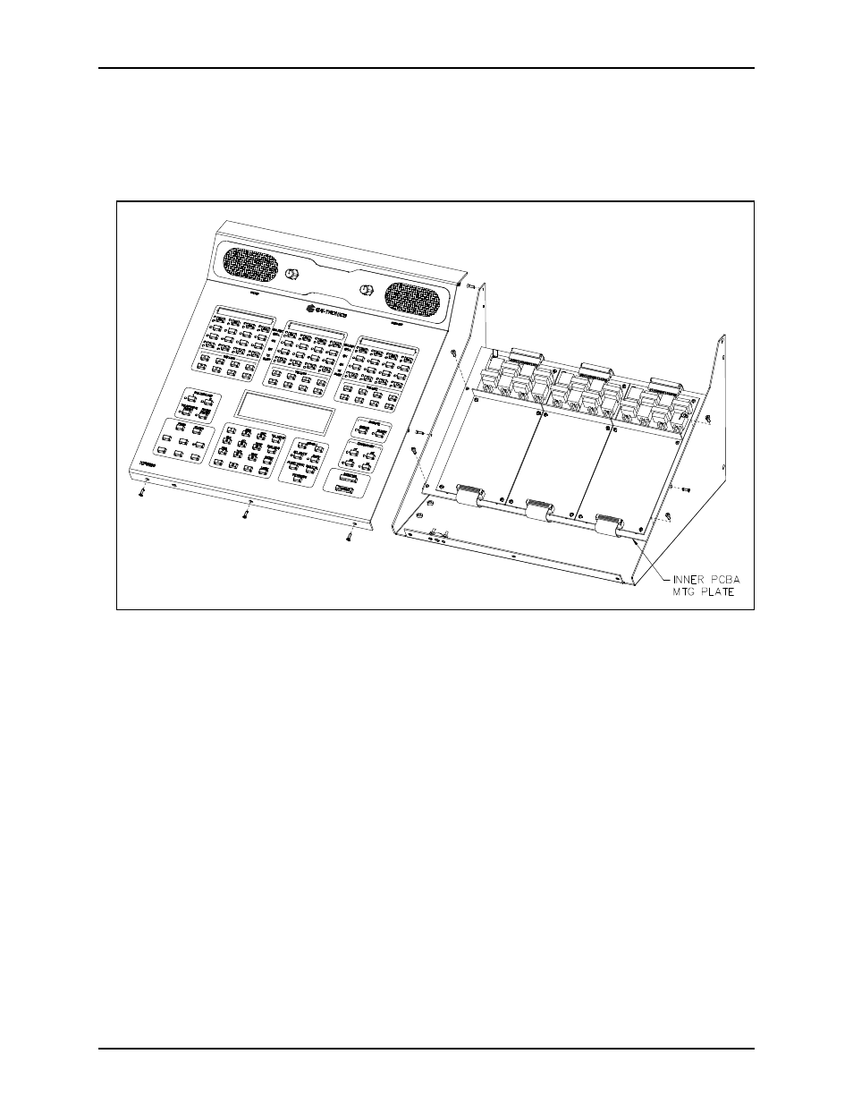
3. Remove the 10 screws securing the side cover panel and gently lift the cover off. See Figure 4.
4. Remove the 4 screws attaching the mounting plate to the base. This allows you to remove the
mounting plate giving you access to the main control PCBA. See Figure 4.
5. Remove the screw in the center of the main control PCBA. Screw in one of the supplied #4-40
male/female standoffs. See Figure 3.
Figure 2.