Installation – GAI-Tronics XCP0070A Direct Enhanced Phone Interface Kit User Manual
Page 2
Pub. 43003-018B
Model XCP0070A Direct Phone Interface Kit
Page: 2 of 5
11/02
Installation
ICP9000 Series Desktop Console
1. Disconnect power from the ICP9000 Series Desktop Console and remove all attached cables from the
rear cover.
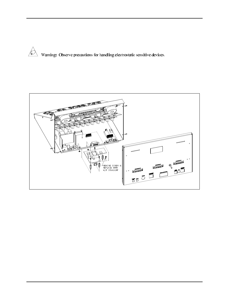
2. Remove the 4 screws securing the rear panel. Gently pull the rear cover from the housing and
disconnect the ribbon cables (SLV-CBL-P) attached to the surge suppression PCBA. Lay the rear
panel flat. See Figure 1. (Do not install the phone PCBA at this point.)
Figure 1.
3. Remove the 7 screws securing the top panel and gently lift the cover exposing the attached speaker
cable and master display cable. See Figure 2.
4. Disconnect the speaker cable at the male-to-female connection point. Unplug the master display
cable from the top cover.
5. Remove the 4 screws attaching the mounting plate to the base. This allows you to remove the
mounting plate giving you access to the main control PCBA. See Figure 2.
6. Remove the screw in the center of the main control PCBA. Screw in one of the supplied #4-40
male/female standoffs. See Figure 1.
7. Attach the remaining two standoffs in the two open holes highlighted by circles on the main control
PCBA. Place the threaded side through the holes and attach the supplied #4-40 nuts to the underside.
See Figure 1.