GAI-Tronics XCP0050A Supervisory Control Kit User Manual
Page 3
Pub. 43003-016B
Model XCP0050A Supervisory Control Kit
Page: 3 of 3
11/02
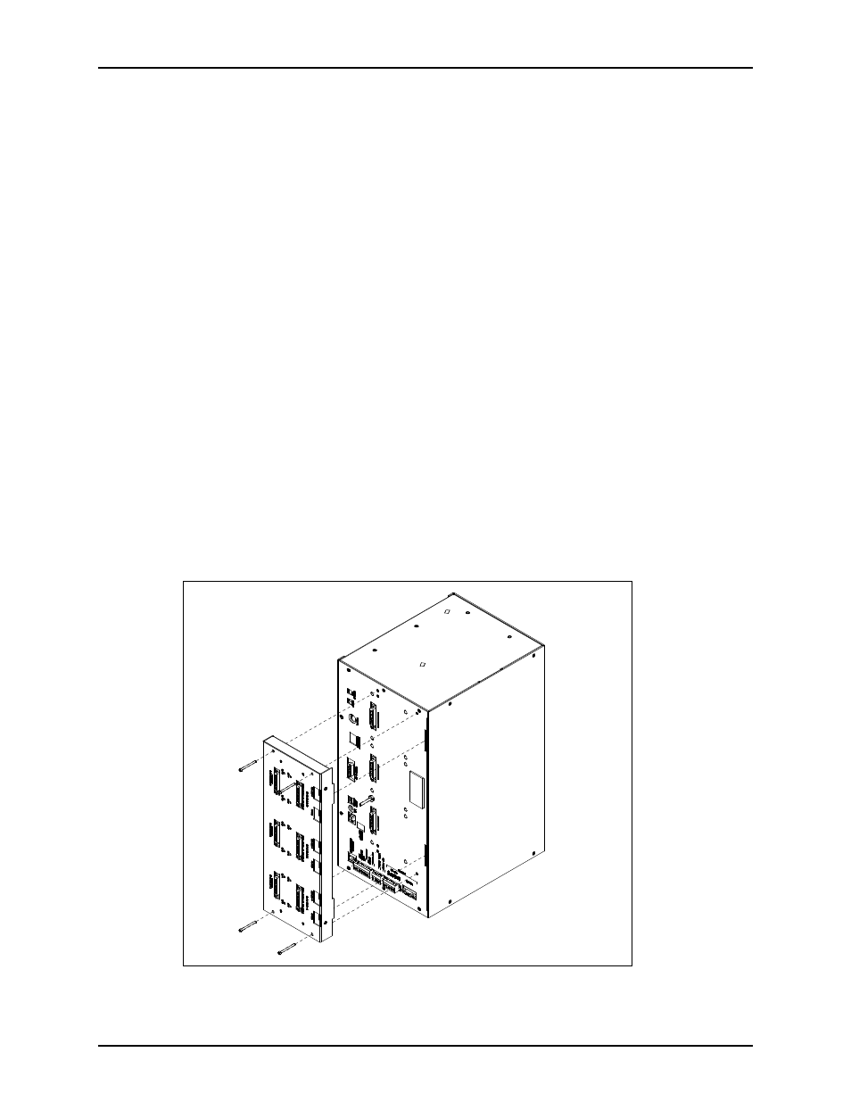
ICP9000 Navigator Series MCU
1. Disconnect power from the ICP9000 Navigator Series MCU and remove all attached cables from the
rear cover.
2. Remove the 8 screws securing the rear panel. Gently pull the rear cover from the housing and
disconnect the ribbon cables (SLV-CBL-P) attached to the surge suppression PCBA. Lay the rear
panel flat.
3. Remove the black rectangular hole plug from the center of the rear cover.
4. Attach the supplied ground cable to the quick-disconnect on the rear of the Supervisory unit. Attach
the other end to the ground screw on the rear panel of the MCU. Bend the tab on the quick-
disconnect on the rear of the Supervisory unit to allow it to sit flush when seated on the connectors.
5. Pull the supervisory cable through the rectangular cut-out on the rear cover, and connect it to P17 on
the main control PCBA in the ICP9000 Navigator Series MCU.
6. Reattach the ribbon cables (SLV-CBL-P) to their matching connectors, and reattach the rear cover.
7. Assemble the Supervisory unit by inserting the two locating tabs into their matching slots on the rear
cover, and attaching it with the four supplied #6-32 pan head machine screws.
8. Reattach all cables and reconnect the power.
9. Refer to the CARD Suite software (XAC1000A) for specific programming instructions for
reconfiguration.
Exploded View of the ICP9000 Navigator Series MCU