Opening the station, Installing the smartseries pcba – GAI-Tronics 12826-001 Hazardous Area ICS SmartSeries PCBA Upgrade Kit User Manual
Page 2
Pub. 42003-258C
M
ODEL
12826-001
H
AZARDOUS
A
REA
ICS
S
MART
S
ERIES
PCBA
U
PGRADE
K
IT
Page
2 of 4
f:\standard ioms - current release\42003 kit manuals\42003-258c.doc
01/14
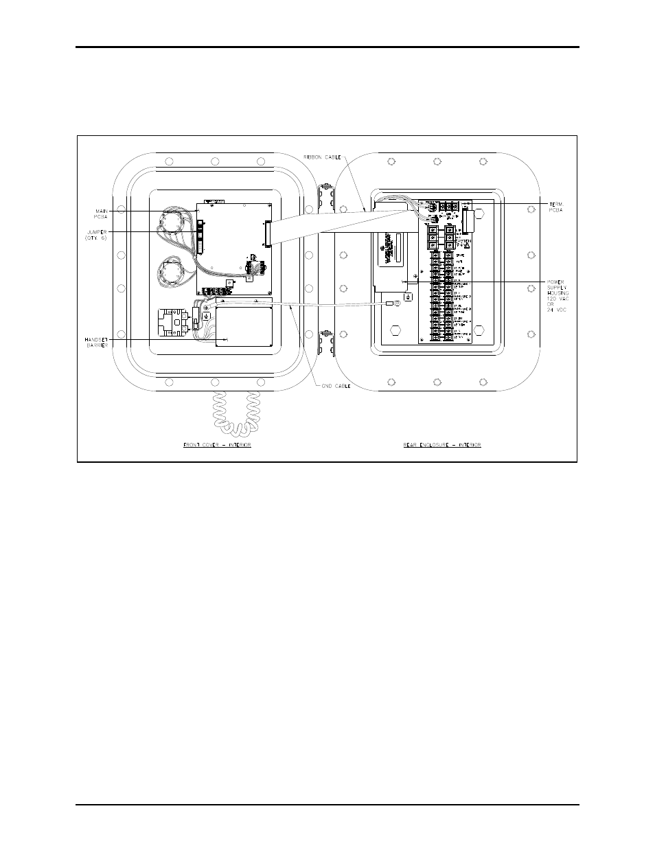
Opening the Station
Remove all cover bolts from the enclosure. Swing the front door open to access the internal PCBAs. See
Figure 1.
Figure 1. ICS Hazardous Area Station – Interior View
Installing the SmartSeries PCBA
1. Unplug the ribbon cable on the Main PCBA at P3.
2. Remove the four screws that secure the Main PCBA to the front cover.
3. Remove the six jumpers on the Main PCBA P4 connector and discard them.
4. Carefully flip over the Main PCBA and attach three nylon standoffs to the board using three 4
5/16
PHTF screws shown in Figure 2. Do not mount the SmartSeries PCBA to the Main PCBA at this
time.
5. Install the provided 34-pin ribbon cable from P4 of the Main PCBA to P4 of the SmartSeries PCBA.
6. Reattach the Main PCBA to the front cover using three of the four screws removed. Use the M/F
standoff in the fourth hole to secure the Main PCBA. See Figure 2.
7. Flip the SmartSeries PCBA over, so that the components are facing down. Secure the SmartSeries
PCBA to the Main PCBA using three of the PHTF screws (provided) for the F/F nylon standoffs and
the 4-40 screw for the one M/F standoff.