Installing new assembly – GAI-Tronics 12512-001 Ind. Tel. Hookswitch Assembly Kit User Manual
Page 2
Pub. 42003-023E
M
ODEL
12512-001
H
OOKSWITCH
A
SSEMBLY
R
EPLACEMENT
K
IT
Page
2 of 8
f:\standard ioms - current release\42003 kit manuals\42003-023e.doc
08/14
4. Cut the cable tie used to bundle wires together.
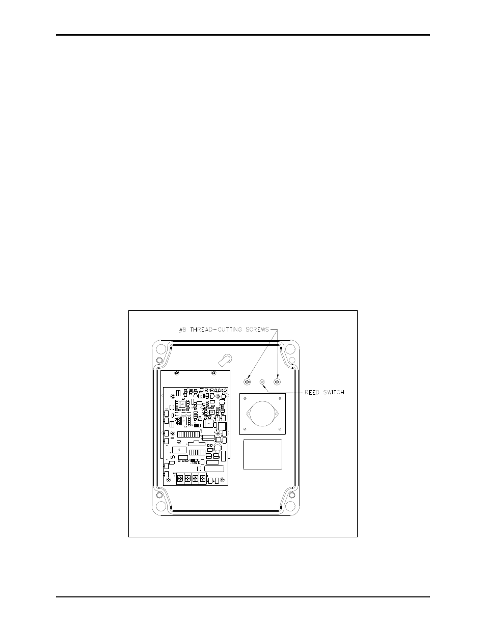
5. Remove the two screws that secure the handset cradle to the front cover. See Figure 1.
6. Pull the handset cradle with the reed switch attached away from the front panel.
7. Remove the handset cradle gasket from the front panel (if necessary).
Installing New Assembly
8. Cut the black wire lead close to the switch body and discard.
9. Thread the blue and white reed switch leads through the center top hole. See Figure 1.
10. Secure the plastic cradle on the front cover using the two #8 thread-cutting screws. See Figure 1.
11. Plug spades on the blue and white wires into E1 and E2 on the PCBA. See Figure 2.
12. Bundle the wires as before with the cable tie included in the kit.
13. Reconnect the red and green wires to TB1. See Figure 2.
14. Replace the front panel and secure using the screws retained from step 1.
15. Test the on-hook/off-hook function to ensure installation has been successful.
Figure 1.
- 370-201, 372A Interface Amplifier Assembly (10 pages)
- 13314-001 and 13314-002 Div. 2 Hazardous Area Speaker Assembly using 13314 Driver (3 pages)
- 230-001 Pole-Mounting Kit (3 pages)
- Electro Sound Electro-Sound Communication System (9 pages)
- 13314-004 Div. 2 Hazardous Area 100-Volt Horn Driver (5 pages)
- XGM003A Gooseneck Microphone Kit (2 pages)
- XGM003A Gooseneck Microphone Kit (26 pages)
- XGM003A Gooseneck Microphone Kit (5 pages)
- 9974 Junction Box (5 pages)
- 232-001 Pole Mounting Kit (3 pages)
- 13411-001 and 13411-002 Replacement Voice Coil / Diaphragm Assemblies (5 pages)
- 726-101 Single Party Desktop Subset (5 pages)
- 726-101 Single Party Desktop Subset (4 pages)
- 478-002 Centra-Page Desktop Subset (6 pages)
- 239WM-002 Slim Wall-Mount Stanchions (5 pages)
- 239WM-002 Slim Wall-Mount Stanchions (6 pages)
- 239WM-002 Slim Wall-Mount Stanchions (4 pages)
- 239WM-002 Slim Wall-Mount Stanchions (4 pages)
- 210-001 Corridor Telephone (10 pages)
- 239WM-002 Slim Wall-Mount Stanchions (10 pages)
- Speaker / Horn Installation for GAI-Tronics Communication System (8 pages)
- 700 Series 120 V AC Page/Party Systems (10 pages)
- 700 Series 24 V DC Page/Party Systems (14 pages)
- 703-002 Multi-Party 24 V DC Amplifier Enclosures (13 pages)
- 703A Indoor Multi-Party 115 V AC Amplifier Enclosure (8 pages)
- 703A Indoor Multi-Party 115 V AC Amplifier Enclosure (3 pages)
- 723-003 24 V DC Remote Handset/Speaker Amplifier (7 pages)
- 723-001 Remote Handset / Speaker Amplifier (3 pages)
- 237-001 Plug-in Power Supply for Telephones (3 pages)
- 733-002 Single Party 24 V DC Amplifier Enclosure (13 pages)
- 7855-001 Explosion-proof Handset Stations (13 pages)
- 7855-002 24 V DC Explosion-proof Page/Party Handset Stations (14 pages)
- 670-001 Explosion-proof Page/Party Speaker Station (9 pages)
- 670-002 24 V DC Explosion-proof Page/Party Speaker Station (10 pages)
- 13351 Integral Loudspeakers (5 pages)
- 305-001 Line Balance Assembly (3 pages)
- 272-001 Intrinsically-Safe Telephones (13 pages)
- 713-102 24 V DC Page/Party Remote Speaker Amplifier (5 pages)
- 263-000 Isolation Barrier Unit (I.S. Phone) (14 pages)
- 774-001 Portable Station Enclosure (Page/Party) (5 pages)
- 234SBA 234SBA Stanchion Broadcast Assembly (12 pages)
- 491-204 Mine Dial / Page Phone (10 pages)
- 773-001 Outdoor Jack Station (Page/Party) (3 pages)
- 491 Series Mine Dial / Page Phone Interface Cabinet (23 pages)
- 268-001 Intrinsically-Safe Telephone Rack-Mount System (14 pages)