Connector pin descriptions – GAI-Tronics XAAB002A Audio Accessory Box User Manual
Page 10
Operation Model
XAAB002A Audio Accessory Box
11/06 6
Connector Pin Descriptions
J1, 8-pin Output Connector, Motorola Standard, Mirrored Connector
J1 is the main output connector to the radio, a console, or an Advanced desk set (towards radio). The
pin-out is mirrored with respect to a Motorola standard 8-pin modular mic jack. See the pin-out below.
N
OTE
: Mirrored pin-out (opposite of pin-to-pin) is used on output connectors so a standard off-the-shelf
male-male modular cable will connect properly.
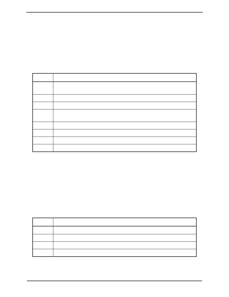
Table 1. J1, 8-Pin Output Connector Pin-out
Pin No. Function
1
RX audio from radio to handset and headset.
Nominal level = 100 mV ac
2
Handset off-hook logic low output towards radio (or console)
3
PTT logic low output towards radio
4
TX audio output towards radio
Nominal level = 80 mV ac
5 Audio
ground
6
Monitor logic output towards radio
7 Not
connected
8
DC power input (from some radios or consoles)
J2, GAI-Tronics Ixx Handset Output, Mirrored Connector
J2 is the GAI-Tronics handset “through-function” output connector. The accessory box can be placed
electrically between the handset and its respective desk set. This enables the audio accessory box to control
handset functions. J2 is mirrored for easy connection to the desk set handset jack. The pin-out for J2 is
shown below.
N
OTE
: Mirrored pin-out (opposite of pin-to-pin) is used on output connectors so a standard off-the-shelf
male-male modular cable will connect properly.
Table 2. J2, GAI-Tronics Handset Output Pin-out
Pin No. Function
1 Audio
ground
2
Handset analog logic functions
3
RX audio from radio. Nominal level = 100 mV ac
4
TX audio towards radio. Nominal level = 25 mV ac