001icsvc, 701-302icsvc & 701-304icsvc, Opening and closing the amplifier, Ics ac-powered page/party – GAI-Tronics 701-302ICS ICS AC-Powered Page/Party Plug-in Amplifiers User Manual
Page 9: Plug-in amplifiers with vlc
Pub. 42004-730L2B
ICS AC-Powered Page/Party
®
Plug-in Amplifiers
Page: 7 of 20
f:\standard ioms - current release\42004 instr. manuals\42004-730l2b.doc
04/11
ICS AC-Powered Page/Party
®
Plug-in Amplifiers with VLC
Models 751-001ICSVC, 701-302ICSVC & 701-304ICSVC
The Volume Level Control (VLC) PCBA allows the amplifier to remotely control the local speaker
volume level. When VLC is activated, a remote device transmits a 50 kHz signal over the page line. The
station detects the 50 kHz signal and switches to an alternate speaker volume setting.
VLC provides an “alternate” speaker volume setting that is activated by receiving a 50 kHz signal on the
page line. Examples of its use are muting office or crew quarters speakers until a high priority message or
alarm is broadcast and/or reducing outdoor speaker volume at night. It can prevent local handset paging
during emergency conditions, and can also provide a relay output, which requires an RTU configuration.
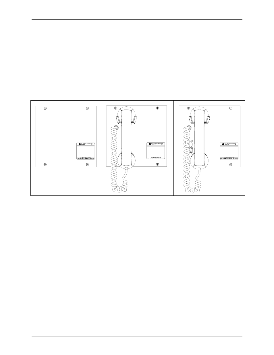
Figure 7. Model 751-001ICSVC
Speaker Amplifier
Figure 8. Model 701-302ICSVC
Handset/Speaker Amplifier
Figure 9. Model 701-304ICSVC
Handset/Speaker Amplifier with
Auxiliary Jack
Opening and Closing the Amplifier
The setting and adjustments vary with each model. Refer to the appropriate section of this manual for the
specific instructions for the applicable model. In some cases, the amplifier must be opened to gain access
to the PCBAs inside. Opening and closing the amplifier is as follows:
1. Place the amplifier on a flat surface and loosen, but do not remove, the two sets of rear cover screws
located on the top and bottom L-shaped slots. See Figure 10.
2. Slide the front panel with the screws sideways and then pull up to separate the front panel from the
rear section. The two sections are connected by a ribbon cable.
3. Lay the rear section to the left and the front section to the right with the PCBAs facing upward for
access to the applicable adjustments.
4. After the adjustments and settings have been made, slide the rear cover L-shaped slots over the top
and bottom screws ensuring no cables are being pinched. Tighten the screws.
- 701-302ICSVC ICS AC-Powered Page/Party Plug-in Amplifiers 701-304ICSVC ICS AC-Powered Page/Party Plug-in Amplifiers 701-904ICS ICS AC-Powered Page/Party Plug-in Amplifiers 751-001ICSVC ICS AC-Powered Page/Party Plug-in Amplifiers 701-304ICS ICS AC-Powered Page/Party Plug-in Amplifiers 701-902ICS ICS AC-Powered Page/Party Plug-in Amplifiers 751-001ICS ICS AC-Powered Page/Party Plug-in Amplifiers 751-901ICS ICS AC-Powered Page/Party Plug-in Amplifiers 701-307ICS ICS DC-Powered Page/Party Plug-in Amplifiers 701-307ICSVC ICS DC-Powered Page/Party Plug-in Amplifiers 701-309ICSVC ICS DC-Powered Page/Party Plug-in Amplifiers 701-909ICS ICS DC-Powered Page/Party Plug-in Amplifiers 751-002ICSVC ICS DC-Powered Page/Party Plug-in Amplifiers 701-309ICS ICS DC-Powered Page/Party Plug-in Amplifiers 701-907ICS ICS DC-Powered Page/Party Plug-in Amplifiers 751-002ICS ICS DC-Powered Page/Party Plug-in Amplifiers 751-902ICS ICS DC-Powered Page/Party Plug-in Amplifiers