Block diagram, Interfaces – GAI-Tronics 751-901 SmartSeries Speaker Amplifier User Manual
Page 5
Pub. 42004-659L2F
751-901
SmartSeries
®
Speaker Amplifier
P
AGE
4 of 11
f:\standard ioms - current release\42004 instr. manuals\42004-659l2f.doc
03/12
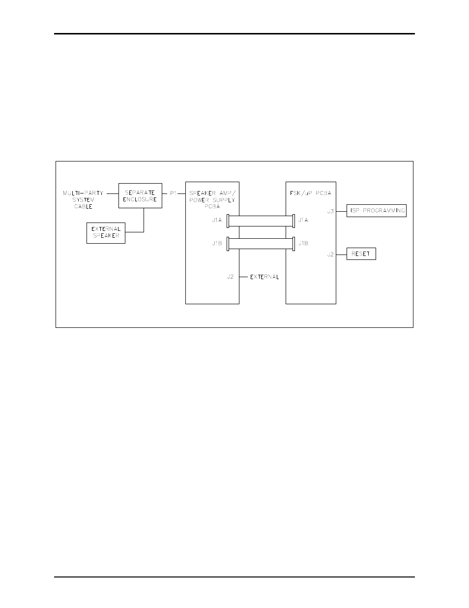
Block Diagram
The P1 connector on the rear of the Speaker Amp/Power Supply PCBA plugs into the socket in an
enclosure connected to the system cable, accessing the Page/Party
®
lines and ac power. Refer to Figure 3.
The Speaker Amp/Power Supply PCBA contains the low voltage power supplies and the speaker
amplifier circuitry.
Connector J1A and J1B on the Speaker Amp/Power Supply connects regulated +5 V dc, +/−15 V dc, and
V
RLY
voltages along with control, monitoring, and line signals to the J1A and J1B on the FSK/
P PCBA.
Connector J2 of the Speaker Amp/Power Supply PCBA connects to optional external devices.
Figure 3. Block Diagram
Interfaces
The assembly interfaces to the system cable, an external loud speaker, and auxiliary devices via P1, a
16-pin connector. All connections to the system cable are made by qualified installation technicians
during the system installation. Direct questions about these connections to the GAI-Tronics Field Service
Department at 800-492-1212 inside the USA or 610-777-1374 outside the USA. Other connections on
the Speaker Amp/Power Supply PCBA provide quick connect/disconnect of subassemblies.
Connector J2 on the bottom of the Speaker Amp/Power Supply PCBA connects to optional devices such
as the SmartSeries
®
RTU installed in specially designed enclosures.