Block diagram – GAI-Tronics 7165-102 SmartSeries Flush-Mount Single and 5-Party Subsets User Manual
Page 4
Pub. 42004-643L2E
Model 716-102 and 7165-102 Flush-Mount Subsets
Page 4 of 10
f:\standard ioms - current release\42004 instr. manuals\42004-643l2e.doc
04/13
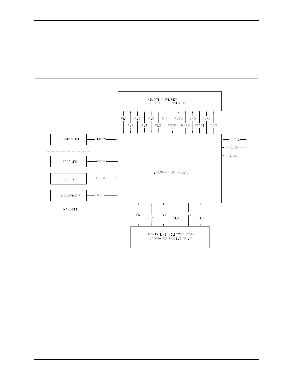
Block Diagram
As shown in Figure 4, the handset, hookswitch, party line switch (Model 7165-102 only), and auxiliary
input (optional) signals connect to the Subset Termination PCBA. The Subset Termination PCBA then
connects these signals to the appropriate terminals of the subset cable for connection to the
amplifier/amplifier enclosure.
Figure 4. Block Diagram
This manual is related to the following products:
See also other documents in the category GAI-Tronics Communication:
- 370-201, 372A Interface Amplifier Assembly (10 pages)
- 13314-001 and 13314-002 Div. 2 Hazardous Area Speaker Assembly using 13314 Driver (3 pages)
- 230-001 Pole-Mounting Kit (3 pages)
- Electro Sound Electro-Sound Communication System (9 pages)
- 13314-004 Div. 2 Hazardous Area 100-Volt Horn Driver (5 pages)
- XGM003A Gooseneck Microphone Kit (2 pages)
- XGM003A Gooseneck Microphone Kit (26 pages)
- XGM003A Gooseneck Microphone Kit (5 pages)
- 9974 Junction Box (5 pages)
- 232-001 Pole Mounting Kit (3 pages)
- 13411-001 and 13411-002 Replacement Voice Coil / Diaphragm Assemblies (5 pages)
- 726-101 Single Party Desktop Subset (5 pages)
- 726-101 Single Party Desktop Subset (4 pages)
- 478-002 Centra-Page Desktop Subset (6 pages)
- 239WM-002 Slim Wall-Mount Stanchions (10 pages)
- 239WM-002 Slim Wall-Mount Stanchions (5 pages)
- 239WM-002 Slim Wall-Mount Stanchions (6 pages)
- 239WM-002 Slim Wall-Mount Stanchions (4 pages)
- 239WM-002 Slim Wall-Mount Stanchions (4 pages)
- 210-001 Corridor Telephone (10 pages)
- Speaker / Horn Installation for GAI-Tronics Communication System (8 pages)
- 700 Series 120 V AC Page/Party Systems (10 pages)
- 700 Series 24 V DC Page/Party Systems (14 pages)
- 703-002 Multi-Party 24 V DC Amplifier Enclosures (13 pages)
- 703A Indoor Multi-Party 115 V AC Amplifier Enclosure (8 pages)
- 703A Indoor Multi-Party 115 V AC Amplifier Enclosure (3 pages)
- 723-001 Remote Handset / Speaker Amplifier (3 pages)
- 723-003 24 V DC Remote Handset/Speaker Amplifier (7 pages)
- 237-001 Plug-in Power Supply for Telephones (3 pages)
- 733-002 Single Party 24 V DC Amplifier Enclosure (13 pages)
- 7855-001 Explosion-proof Handset Stations (13 pages)
- 7855-002 24 V DC Explosion-proof Page/Party Handset Stations (14 pages)
- 670-001 Explosion-proof Page/Party Speaker Station (9 pages)
- 670-002 24 V DC Explosion-proof Page/Party Speaker Station (10 pages)
- 13351 Integral Loudspeakers (5 pages)
- 305-001 Line Balance Assembly (3 pages)
- 272-001 Intrinsically-Safe Telephones (13 pages)
- 713-102 24 V DC Page/Party Remote Speaker Amplifier (5 pages)
- 263-000 Isolation Barrier Unit (I.S. Phone) (14 pages)
- 774-001 Portable Station Enclosure (Page/Party) (5 pages)
- 234SBA 234SBA Stanchion Broadcast Assembly (12 pages)
- 491-204 Mine Dial / Page Phone (10 pages)
- 773-001 Outdoor Jack Station (Page/Party) (3 pages)
- 491 Series Mine Dial / Page Phone Interface Cabinet (23 pages)
- 268-001 Intrinsically-Safe Telephone Rack-Mount System (14 pages)