Troubleshooting, Specifications – GAI-Tronics 12593-101 Redundant PPI Switching Module User Manual
Page 5
Pub. 42004-474A
Model 12593-101 Redundant PPI Switching Module
Page 5 of 5
f:\standard ioms - current release\42004 instr. manuals\42004-474a.doc
04/13
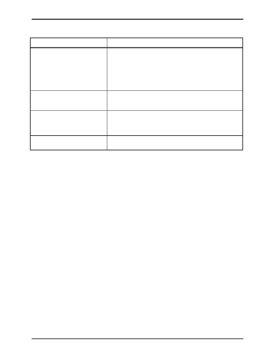
Troubleshooting
Problem Solution
SmartSeries station faults are
present in the secondary system.
Verify 12 V dc power is applied to the module.
Verify CPU PCBA address is set to FF.
Verify cables are properly inserted into connectors J1, J2, J3.
Ensure pins of CPU PCBA are correctly inserted into J4 of
lower relay switching PCBA.
SmartSeries stations squeal
when party line 1 or 2 are
accessed.
Verify connectors J1, J2, J3 are properly inserted. If
disconnected, the page, and party lines 1 and 2 will be unloaded
resulting in oscillation of the SmartSeries handset amplifier.
Module LEDs do not illuminate
and relays do not switch when
input control is provided.
Verify 12 V dc power is applied to the module.
Verify 12 V dc (−) is being switched to the C
ONTROL
inputs
at TB2.
Module still does not function after
all checks described in this section.
Contact GAI-Tronics service for repair or replacement of the
module.
Specifications
Electrical
Power requirements ............................................................... 10.8–13.2 V dc (12 V dc @ 265 mA nominal)
Number of control inputs ............................................................................................................................. 1
Number of fault outputs ............................................................................................................................... 1
Fault output type .......................................................................................................... Form “C” dry contact
Fault output contact rating .................................................................................... 1 A maximum @ 30 V dc
Connections
RJ45 jack ...................................................................................................................................................... 3
Modular (plug-in) terminal blocks ............................................................................................................... 3
Minimum terminal block conductor size .................................................................. No. 28 AWG (0.5 mm
2
)
Maximum terminal block conductor size .................................................................. No. 12 AWG (3.0 mm
2
)
Mechanical
Module dimensions ........................................ 4.00 L
4.00 W 1.56 H inches (101.6 101.6 39.7 mm)
Module weight .................................................................................................................. 0.43 lbs. (0.20 kg)
Environmental
Temperature range (operating/storage) .................................................... −4
F to 158 F (−20 C to 70 C)
Humidity .......................................................................................... 85% non-condensing relative humidity