GAI-Tronics 12599-002 Hot Standby Amplifier Module User Manual
Page 6
Pub. 42004-412A
Model 12599-002 Hot Standby Amplifier Module
Page: 6 of 17
\\s_eng\gtcproddocs\standard ioms - current release\42004 instr. manuals\42004-412a.doc
06/08
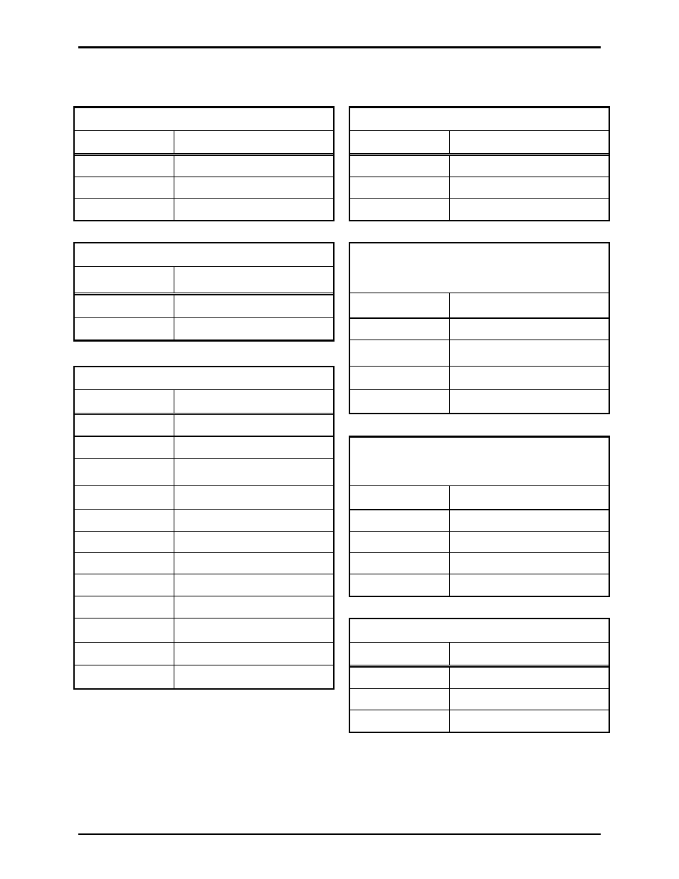
The following is a summary of all terminal block function(s). Number references shown in the following
tables are from right to left when viewed from the edge of the module.
TB1 – 12 V dc Power Input
TB4 – Amp-1 Fault Contact Output
Terminal Ref. Function
Terminal Ref. Function
1
12 V dc positive (+)
1
Normally Open Contact
2
12 V dc negative (-)
2
Normally Closed Contact
3 Ground
(optional)
3 Common
Contact
TB2 – 12 V dc Output
Terminal Ref. Function
TB5 – Input and Source
Amp-1 (Single Channel Mode)
Amp-1, Ch-1 (Dual Channel Mode)
1
12 V dc positive (+)
Terminal Ref. Function
2
12 V dc negative (-)
1
Amplifier Input (+)
2
Amplifier Input (-)
TB3 – Amplifier Fault Control Inputs
3
Audio Signal Source (+)
Terminal Ref. Function
4
Audio Signal Source (-)
1
Amp-1 Fault Input (+)
2
Amp-1 Fault Input (-)
3
Amp-2 Fault Input (+)
TB6 – Output and Speaker
Amp-1 (Single Channel Mode)
Amp-1, Ch-1 (Dual Channel Mode)
4
Amp-2 Fault Input (-)
Terminal Ref. Function
5
Amp-3 Fault Input (+)
1
Amplifier Input (+)
6
Amp-3 Fault Input (-)
2
Amplifier Input (-)
7
Amp-4 Fault Input (+)
3
Audio Signal Source (+)
8
Amp-4 Fault Input (-)
4
Audio Signal Source (-)
9
Amp-5 Fault Input (+)
10
Amp-5 Fault Input (-)
TB7 – Amp-2 Fault Contact Output
11
Amp-6 Fault Input (+)
Terminal Ref. Function
12
Amp-6 Fault Input (-)
1
Normally Open Contact
2
Normally Closed Contact
3 Common
Contact