GAI-Tronics 234L(x)-xxx LITE Series Stanchions User Manual
Page 15

Pub. 42004-393B
Model 234L(x)-xxx LITE Series Stanchion
Page: 14 of 18
\\s_eng\gtcproddocs\standard ioms - current release\42004 instr. manuals\42004-393b.doc
03/07
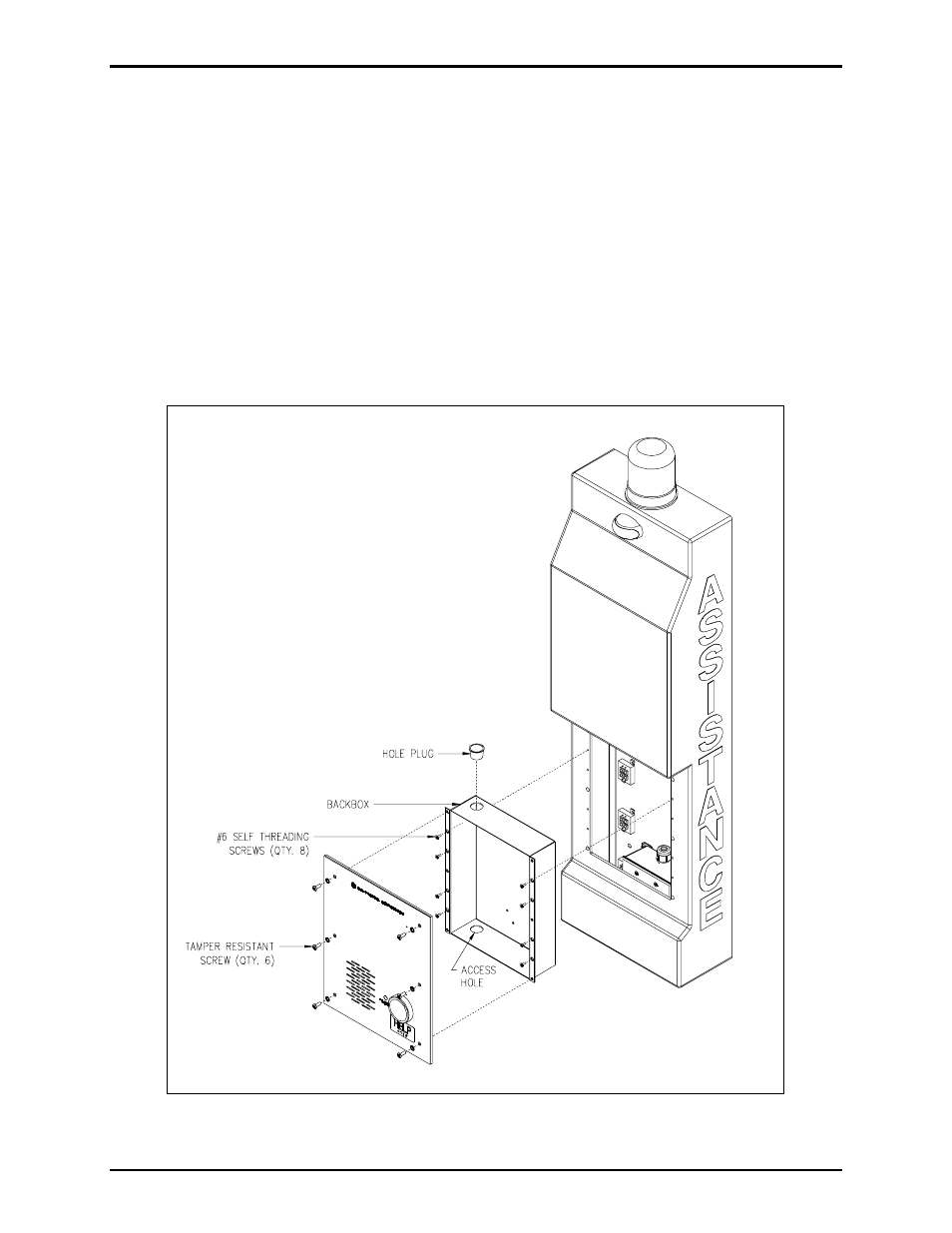
5. Place the back box into the phone opening from the front of the stanchion. Mount the box using the
eight 6-32 self-tapping flat head screws supplied in the stanchion’s parts envelope. Refer to Figure 9.
6. The telephone front panel is shipped from the factory with a cable and modular plug attached to TB1.
If the telephone line is to be hard-wired to the phone, this cable can be removed and discarded. Skip
to step 7. If desired, an optional modular telephone jack can be mounted to the inside of the back box
allowing the use of the cable and modular plug that is attached to TB1.
7. Bring the cable lead from the relay PCBA through the access hole of at the bottom of the back box for
connection to the telephone PCBA.
8. Attach the telephone’s cable lead to TB2 (out) on the telephone PCBA as shown in Figure 5.
9. Install the phone’s front panel using the six tamper-resistant screws and six washers provided with the
phone. Figure 9. Do not over-tighten. Excessive tightening will cause the panel to warp.
Figure 9. Telephone Installation
- 370-201, 372A Interface Amplifier Assembly (10 pages)
- 13314-001 and 13314-002 Div. 2 Hazardous Area Speaker Assembly using 13314 Driver (3 pages)
- 230-001 Pole-Mounting Kit (3 pages)
- Electro Sound Electro-Sound Communication System (9 pages)
- 13314-004 Div. 2 Hazardous Area 100-Volt Horn Driver (5 pages)
- XGM003A Gooseneck Microphone Kit (5 pages)
- XGM003A Gooseneck Microphone Kit (2 pages)
- XGM003A Gooseneck Microphone Kit (26 pages)
- 9974 Junction Box (5 pages)
- 232-001 Pole Mounting Kit (3 pages)
- 13411-001 and 13411-002 Replacement Voice Coil / Diaphragm Assemblies (5 pages)
- 726-101 Single Party Desktop Subset (5 pages)
- 726-101 Single Party Desktop Subset (4 pages)
- 478-002 Centra-Page Desktop Subset (6 pages)
- 239WM-002 Slim Wall-Mount Stanchions (6 pages)
- 239WM-002 Slim Wall-Mount Stanchions (4 pages)
- 210-001 Corridor Telephone (10 pages)
- 239WM-002 Slim Wall-Mount Stanchions (10 pages)
- 239WM-002 Slim Wall-Mount Stanchions (5 pages)
- Speaker / Horn Installation for GAI-Tronics Communication System (8 pages)
- 700 Series 120 V AC Page/Party Systems (10 pages)
- 700 Series 24 V DC Page/Party Systems (14 pages)
- 703-002 Multi-Party 24 V DC Amplifier Enclosures (13 pages)
- 703A Indoor Multi-Party 115 V AC Amplifier Enclosure (8 pages)
- 703A Indoor Multi-Party 115 V AC Amplifier Enclosure (3 pages)
- 723-001 Remote Handset / Speaker Amplifier (3 pages)
- 723-003 24 V DC Remote Handset/Speaker Amplifier (7 pages)
- 237-001 Plug-in Power Supply for Telephones (3 pages)
- 733-002 Single Party 24 V DC Amplifier Enclosure (13 pages)
- 7855-001 Explosion-proof Handset Stations (13 pages)
- 7855-002 24 V DC Explosion-proof Page/Party Handset Stations (14 pages)
- 670-001 Explosion-proof Page/Party Speaker Station (9 pages)
- 670-002 24 V DC Explosion-proof Page/Party Speaker Station (10 pages)
- 13351 Integral Loudspeakers (5 pages)
- 305-001 Line Balance Assembly (3 pages)
- 272-001 Intrinsically-Safe Telephones (13 pages)
- 713-102 24 V DC Page/Party Remote Speaker Amplifier (5 pages)
- 263-000 Isolation Barrier Unit (I.S. Phone) (14 pages)
- 774-001 Portable Station Enclosure (Page/Party) (5 pages)
- 234SBA 234SBA Stanchion Broadcast Assembly (12 pages)
- 491-204 Mine Dial / Page Phone (10 pages)
- 773-001 Outdoor Jack Station (Page/Party) (3 pages)
- 491 Series Mine Dial / Page Phone Interface Cabinet (23 pages)
- 268-001 Intrinsically-Safe Telephone Rack-Mount System (14 pages)