Wiring, Station wiring – GAI-Tronics 400-001 RigCom Stations User Manual
Page 6
Pub. 42004-376C
Model 400-001 and 400-002NS RigCom Stations
Page 6 of 22
e:\standard ioms - current release\42004 instr. manuals\42004-376c.doc
04/14
Wiring
Station Wiring
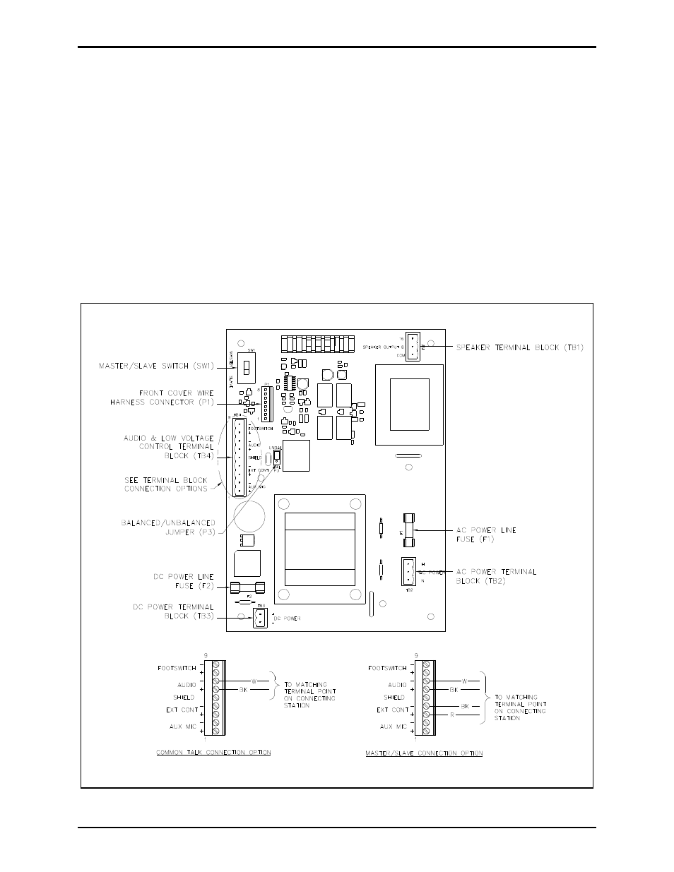
Attach the conduit or cable glands to the ¾-inch NPT holes on the bottom of the enclosure. Feed the low-
voltage wiring conduit on the left side hole, from front view, and the power wiring through the right side
hole, from front view. Attach the wires to the terminal blocks located on the PCBA within the enclosure.
See Figure 4 and charts for connection points and descriptions.
If using the 10438-001 Auxiliary Microphone Assembly, connect the assembly to the station at terminal
block TB4-1 (+) and TB4-2 (–), shield to TB4-5, if used. The maximum distance from the station is 50
feet using No. 18 AWG wire.
If using the 51052-003 Auxiliary Footswitch Assembly, connect the assembly to the station at terminal
block TB4-8 (+) and TB4-9 (–), shield to TB4-5, if used. The maximum distance from the station is 50
feet using No. 18 AWG wire.
Figure 4. RigCom Station PCBA