Model 247-001 – GAI-Tronics 227-001 Auto-dial Telephones User Manual
Page 6
Pub. 42004-338F
Model 227-001, 247-001, 257-001, and 277-001 Industrial Auto-dial Telephones
Page 6 of 19
f:\standard ioms - current release\42004 instr. manuals\42004-338f.doc
06/12
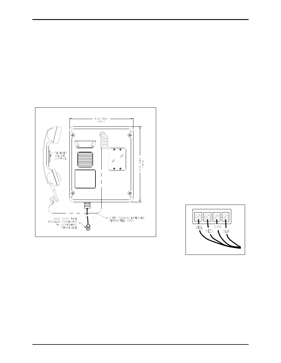
Model 247-001
1. Remove the four front panel screws using a standard Phillips screwdriver, and remove the front panel
assembly and set aside. Disconnect the 7-foot half-modular telephone cord from the PCBA terminal
strip (if connected). See Figure 7.
2. Please refer to Figure 1 and Figure 2 if utilizing conduit for cable installation. If using the gland
bushing provided with the unit, drill a 0.688-diameter hole at either drill spot on the bottom of the
rear enclosure.
3. Push the free end of the telephone cord through the gland bushing using needle-nose pliers. Allow 8–
10 inches of telephone cord to extend past the bushing. Tighten the bushing around the cord. Feed
the free end of the telephone cord
through the hole in the enclosure.
4. Secure the bushing in the hole with the
supplied locknut using a 7/8-inch
wrench and channel locks to tighten.
5. There are four mounting holes in the
rear enclosure. Mount the enclosure to
the wall using either four 1/4-20
machine screws with nuts and
washers, or #14 wood screws of
appropriate length for the mounting
surface. Refer to Figure 8.
6. Connect the telephone cord to the
PCBA terminal strip. See Figure 7.
7. Replace the front panel assembly, and secure with the four front
panel screws.
8. Connect the telephone cord’s modular connector to the incoming subscriber line using the appropriate
mating connector.
9. Check for proper telephone operation by calling to and from another telephone.
Figure 6. Model 247-001 Outline Drawing
Figure 7. PCBA Connection