Head table operation – FSR ML-116 User Manual
Page 34
FSR
ML-116 INSTALLATION DATA
Telephone 973-785-4347
page 33
HEAD TABLE OPERATION
The head table switches on the MAP panel control relays that switch speakers located over a head
table location, on or off. When the head table switch is activated those aforementioned speakers are
disconnected whenever the microphone is in use, to eliminate audio feedback, and are connected in
all other modes of operation.
The installation of the head table controls requires the HTBC card along with the associated HT-8
cards be located in the rear of the rack housing the power amplifiers. Each HT-8 module contains
relays for eight head table locations. The ML-116 system has provisions to handle up to 32 head
table positions meaning an installation could have up to 4 HT-8 modules. All these modules come
mounted in an FSR TRAC-BRAC which facilitates rear rack mounting.
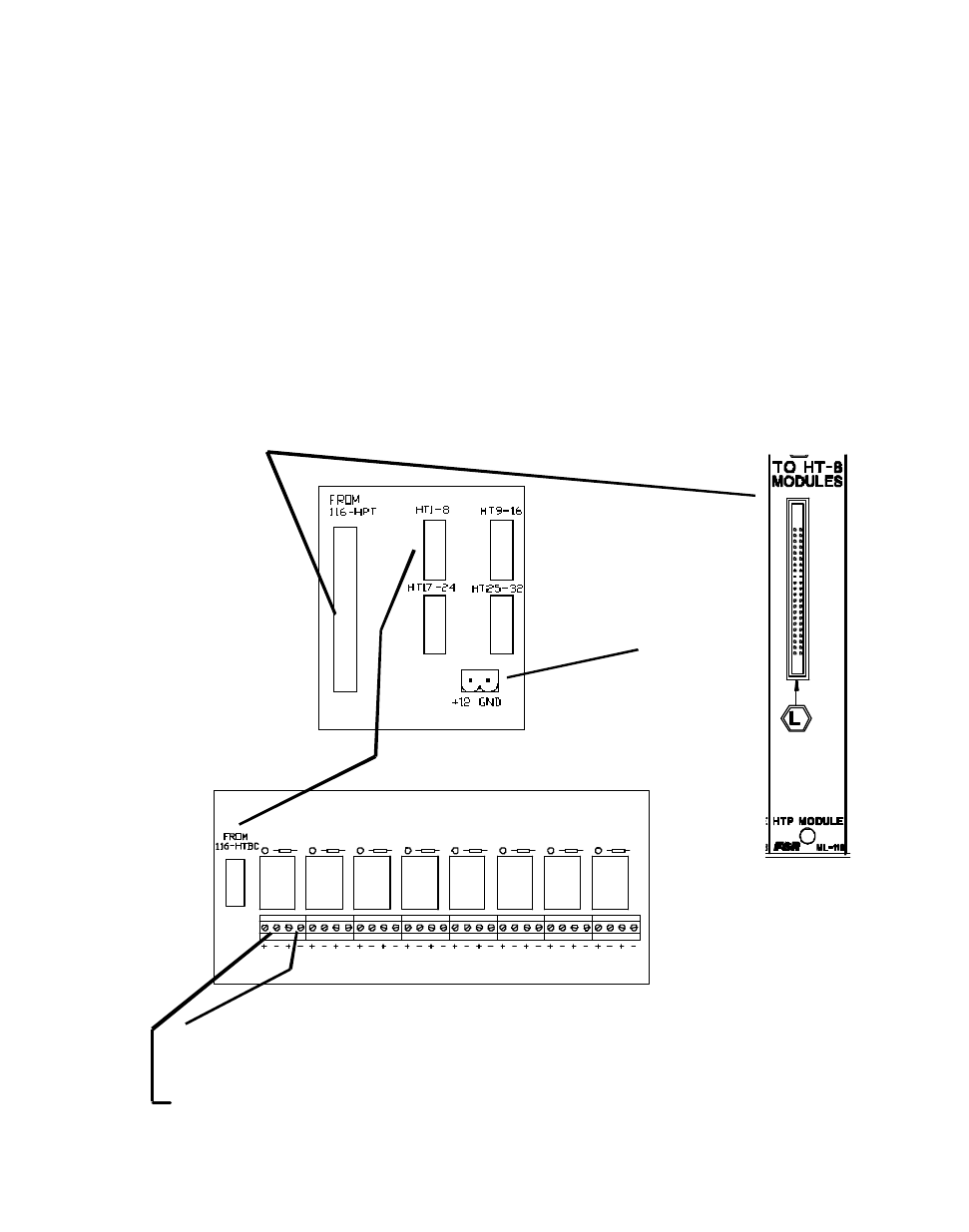
All the interconnect cables from the ML-116 ACU to the HTBC and from the HTBC to the HT-8
cards are supplied with the system.
partial view of the
HTP module
(rear of ACU)
Head Table Hookup Diagram (only one HT-8 is shown, there could be a total of 4)
from wallmount trans-
former (supplied) ML-HT
speaker line output to the speakers above the head table location in room 1
from amplifier output for room 1 in the system
RM
1
RM
2
RM
3
RM
4
RM
5
RM
6
RM
7
RM
8
HT-8 BOARD
HTBC BOARD