Chapter 2 installation instructions – Foxconn RC4107MA-8KRS2 User Manual
Page 26
Chapter 2 Installation Instructions
19
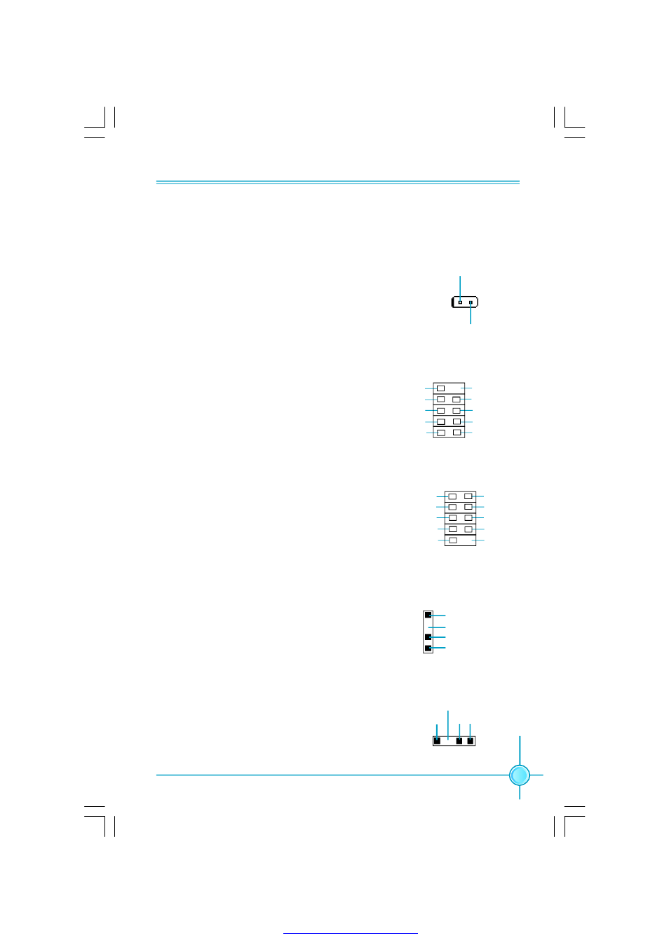
Chassis Intruder Connector: INTR
The connector connects to the chassis security switch
on the case. The system can detect the chassis intru-
sion through the status of this connector. If the connec-
tor has been closed once, the system will send a
message. To utilize this function, set “Case Open Warn-
ing” to “Enabled” in the “PC Health Status” section of
the CMOS Setup. Save and exit, then boot the operating
system once to make sure this function takes effect.
INTR
1
2
INTRUDERJ
GND
Addtional COM Connector: COM2
This motherboard provides an additional
serial COM connector for your machine.
Connect one side of a switching cable to the
connector, then attach the serial COM device
to the other side of the cable.
SOUT
GND
RLSD
RI#
DTR#
DSR#
SIN
9
10
1
2
CTS#
RTS#
COM2
Empty
S/PDIF Out Connector: SPDIF OUT
The S/PDIF out connector is capable of provid-
ing digital audio to external speaker or com-
pressed AC3 data to an external Dolby digital
decoder.
Note: The empty pin of SPDIF cable should be
aligned to empty pin of S/PDIF out connector.
1
GND
SPDIF OUT
1
SPDIF_OUT
Empty
5V
1394 Connector: F_1394(optional)
The 1394 expansion cable can be con-
nected to either the front (provided that the
front panel of your chassis is equipped
with the appropriate interface) or rear panel
of the chassis.
+12V
GND
TPB -
GND
TPA -
F_1394
1
2
9
10
+12V
TPB +
GND
Empty
TPA +
Speaker Connector: SPEAKER(optional)
The speaker connector is used to connect
speaker of the chassis.
1
SPK(Pull high)
SPKJ
Empty
NC
SPEAKER
PDF 文件使用 "pdfFactory" 试用版本创建