Foxconn RC4107MA-8KRS2 User Manual
Page 12
5
Chapter 1 Product Introduction
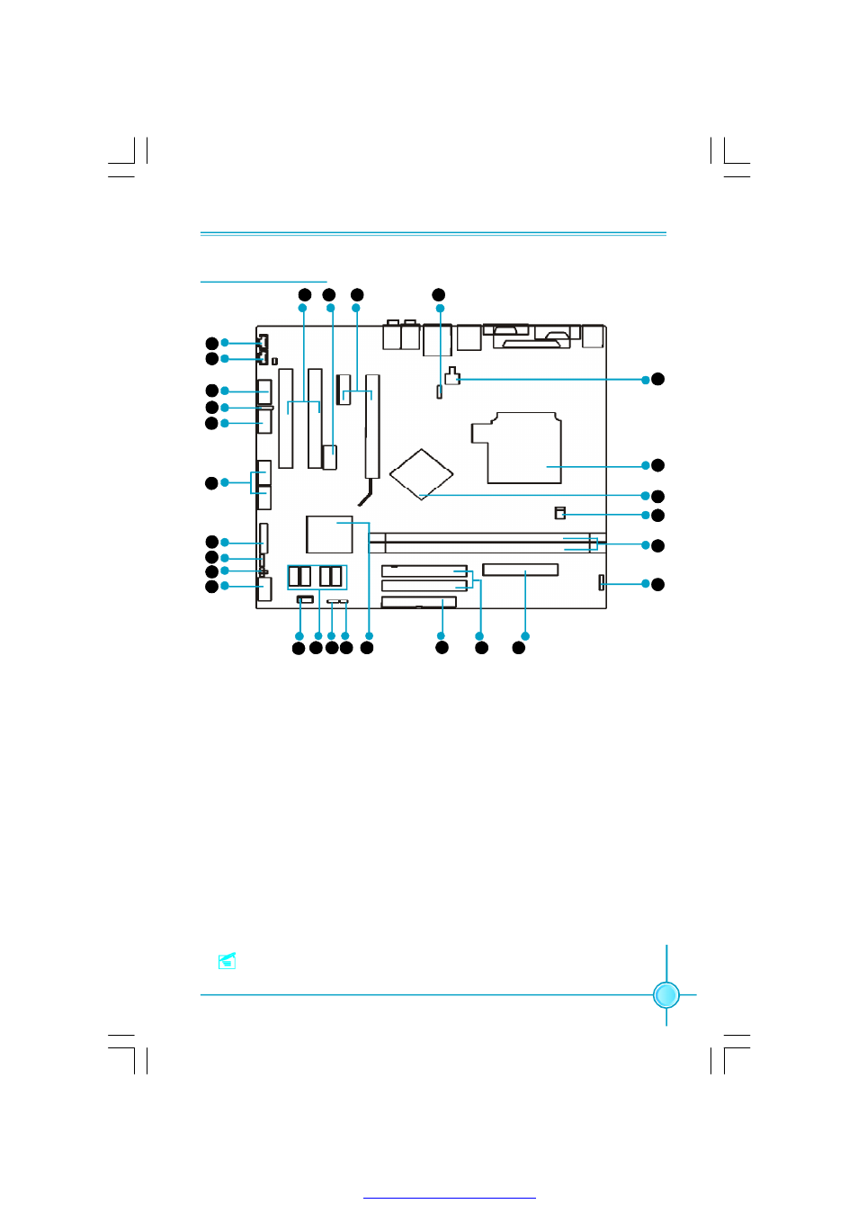
Motherboard Layout
Note: The above motherboard layout is provided for reference only;
please refer to the physical motherboard.
15. South Bridge: SB450
16.FDD Connector
17.ATA 133/100/66/33 IDE Connectors
18.24-pin ATX Power Connector
19.IrDA Connector
20.DIMM Slots
21.CPU Fan Connector
22. North Bridge: RC410
23.CPU Socket
24.4-pin 12V ATX Power Connector
25.TV OUT Connector(optional)
26.PCI Express Slots
27.1394 Connecotr(optional)
28.PCI Slots
1.AUX_IN Connector (optional)
2.CD_IN Connector
3.Front Audio Connector
4.SPDIF_OUT Connector
5.COM2 Connector
6.USB Connectors
7.TPM Connector
8.Speaker Connector(optional)
9.BIOS protection Jumper(optional)
10.Front Panel Connector
11.System Fan Connector
12.Serial ATA Connectors
13.Clear CMOS Jumper
14.Chassis Intruder Connector
1
2
3
4
5
6
7
8
12
11
13 14 15
16
17
18
19
20
21
22
23
7
24
9
10
25
26
27
28
PDF 文件使用 "pdfFactory" 试用版本创建