Fluke Biomedical 35080M User Manual
Page 25
35080M
Operators Manual
4-4
2. Oscilloscope Setup - Connect the kVp Divider to the scope using a shielded cable and set the
vertical sensitivity set to 0.5 volts per division. With the scope input in the GROUND position,
adjust the vertical position control to place the trace on the bottom graticule line. Next, set the
scope in single trace, storage mode and place the input selector switch in the DC position.
3. 25 kVp Measurement Procedure - Set the X-ray generator for 25 kVp and 100 mA. If not
available, use at least 50 mA and a minimum time of 50 msec or a mAs setting that provides these
tube currents. Select the Mo (molybdenum) filter and make an exposure while adjusting the scope
trigger level as necessary to get a stable trace. After measuring the peak voltage, record the value.
5. 26 kVp Measurement Procedure - Set the generator for 26 kVp and make an exposure. Record
this value also. (The two voltage values should be equal to within ± 0.020 V. If so, this will be your
BASE VOLTAGE; if not, then repeat steps 3 and 4 at 24 and 25 kVp respectively.)
5. 29 kVp Measurement Procedure - Set the generator for 29 kVp and make an exposure. (If this
voltage is greater than the BASE VOLTAGE by 0.1 V to 0.25 V, record this new voltage value. If
this voltage is greater than the BASE VOLTAGE by higher than 0.25 V, repeat this step at one kVp
lower; on the other hand, if this voltage is not greater than the BASE VOLTAGE by 0.1 V, repeat
this step at one kVp higher).
6. Subtract the BASE VOLTAGE from the voltage measured in step 5. Multiply this voltage by 10 and
add 27.0 to determine the true kVp for this station.
7. Proceed to Section 5.5 (Linear Mammo Filter Pack Operating Instructions).
Example
1: DC Mammographic Generator
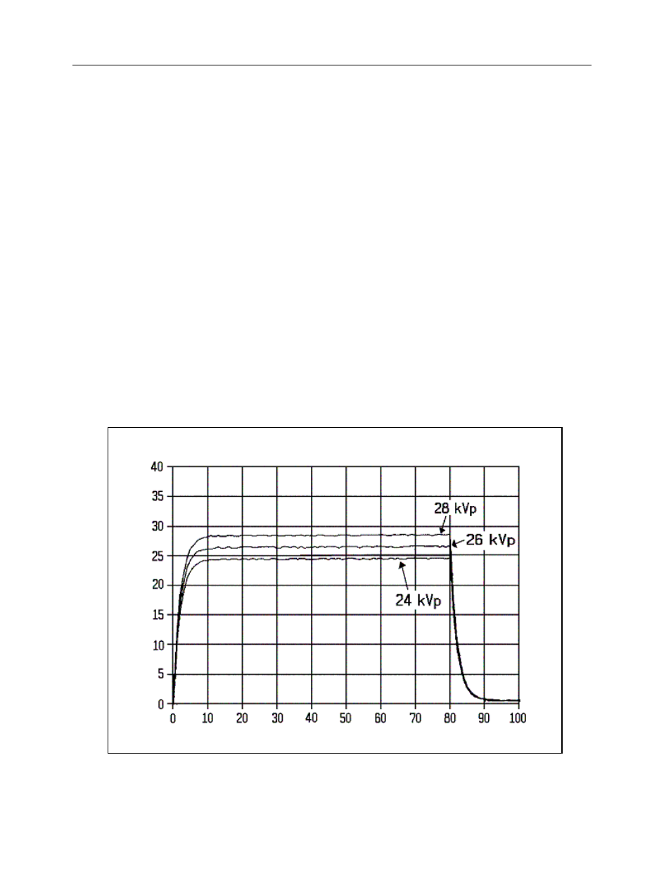
Figures 4-4 and 4-5 show the input and output waveform obtained from exposures taken at 24, 26,
and 28 kVp respectively. The baseline value of 3.10 V can be seen from the lower pair of traces on
Figure 4-5. The level measured on the upper trace is 3.20 V. The kVp corresponding to this trace
is calculated as:
kVp = 27.0 + [10*(3.20-3.10)] = 28.0
Figure 4-4.
DC Mammographic Generator Input Waveforms
Input Kilovolts
Generator Input
DC Generator 24 kV, 26 kV, 28
Milliseconds