Wiring, Basic settings – Flowserve URB 2 User Manual
Page 12
2
Wiring
– continued –
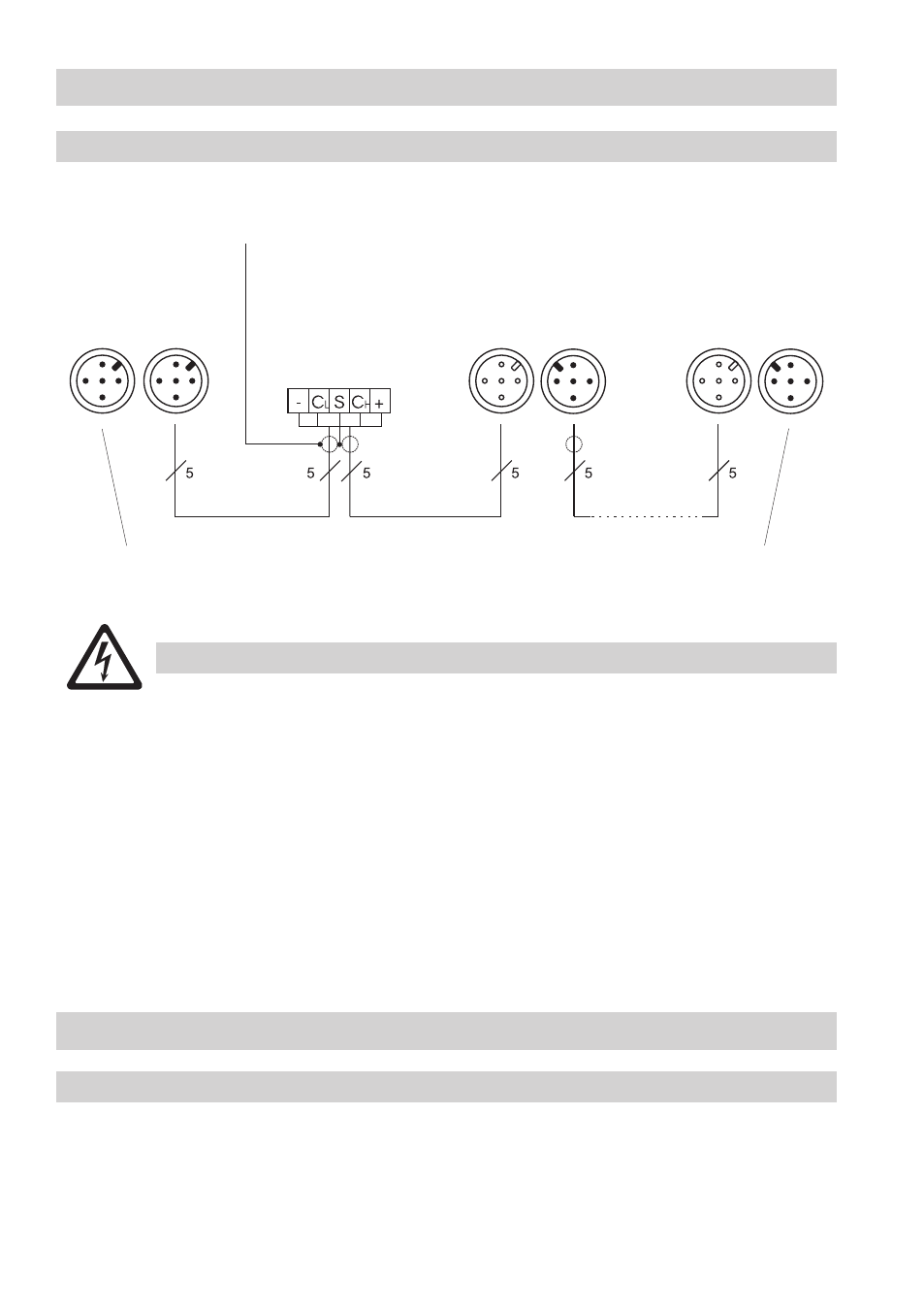
Wiring diagram for CAN bus system – example –
Attention
■
Wire equipment in series. Star-type wiring is not permitted!
■
Connect screens of the bus cables
once to the central earthing point (CEP).
■
If two or more system components are connected in a CAN bus system, the first and
the last device
must be provided with a terminating resistor of 20
Ω
(terminal
C
L
/C
H
). We recommend that you use the URB 2 with a connecting socket equipped with
terminating resistor either as first or as last device.
■
Only one operating and display unit URB 2 may be used per CAN bus network.
■
The CAN bus system must not be interrupted during operation.
In the event of an interruption a malfunction alarm is raised.
■
The operating and display unit URB 2 must not be applied in parallel with the operating,
display & automatic control device SPECTORcontrol.
Basic Settings
Factory setting
Operating & display unit URB 2
The operating and display unit URB 2 unit features the following factory set default values:
■
Node ID: 60
■
Baud rate: 250 kBit/s (25 m cable length)
Fig. 6
Connecting socket with
terminating resistor 20 Ω
Plug with terminating
resistor 20 Ω
Central
earthing point
CEP
Control unit
NRS -4x
NRS 2-40
NRR 2-40
LRR -40
TRS 5-40
Operating device
URB 2
Level electrode
Conductivity
electrode
NRG x6-4x
LRG xx-4x
Temperature
transmitter
TRV 5-40