Double-action positioner (direct function), Electrical connections – Flowserve Pulsair III Digital User Manual
Page 8
14
Worcester Controls Pulsair III Digital Electronic Positioner FCD WCAIM2056-00 - 08/04
fl owserve.com
15
Worcester Controls Pulsair III Digital Electronic Positioner FCD WCAIM2056-00 - 08/04
Double-Action Positioner (Direct Function)
Double-Action Actuator
When the control signal increases, the pressure C+ to the actuator is increased. The
valve stem is pressed upward and rotates the positioner spindle counterclockwise.
When the control signal is reduced, the pressure C- to the actuator increases and the
valve stem is pressed downward. If the control signal disappears, the pressure goes to
C-, C+ vents, and the valve closes.
C–
S
C+
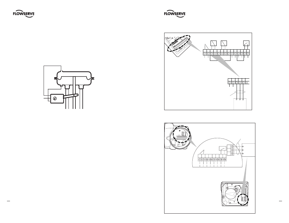
Electrical Connections
The diagrams on the next page show the terminal blocks in the Pulsair III W and Z.
Remote Unit
The remote unit shall be connected between terminals 3, 4 and 5 in the Pulsair III and 3,
4 and 5 in the remote unit. Use a shielded cable and ground it in the Pulsair III only. The
maximum recommended distance between the Pulsair III and the remote unit is 16 ft.,
5 in. (5 m).
Note: When converting a Pulsair III W or Z for use with a remote unit, some changes
have to be done inside the positioner, see section 8.
a
Warning: In a hazardous environment where there is a risk of explosion,
electrical connections must comply with the relevant regulations.
Terminal Blocks
The terminal blocks in the illustrations at right are accessible when the terminal cover is
removed, see Section 8 for disassembly instructions.
a
Warning: In a hazardous environment where there is a risk of explosion,
electrical connections must comply with the relevant regulations.
Pulsair III W
Option
HART –
connection
1
4-20 mA + input signal
2
4-20 mA – input signal
3
Switch 1 NO
4
Switch 1 NC
5
Switch 1 COM
6
Switch 2 NO
7
Switch 2 NC
8
Switch 2 COM
9
AUX input 4-20 mA +
10 AUX input 4-20 mA –
11 4-20 mA + Feedback
12
4-20 mA – Feedback
13 Alarm output +
14 Alarm output –
+ –
+ – + – + –
1
2
3
4
5
6
7
8
9
10
11
12 13
14
Remote
unit
+ –
1
2
3
4
5
6
3
4
5
Shielded cables,
grounded in the
Pulsair III unit
Connecting a
remote unit
Pulsair III Z
1
4-20 mA + input signal
2
4-20 mA – input signal
3
Switch 1 NO (Remote unit)
4
Switch 1 NC (Remote unit)
5
Switch 1 COM (Remote unit)
9
AUX input 4-20 mA +
10 AUX input 4-20 mA –
11 4-20 mA +
12 4-20 mA –
13 Alarm output +
14 Alarm output –
Optional
Shielded cables,
grounded on the
Pulsair III unit
3
4
HART
Connection
Remote
Unit
5