4 variants, 5 function, Pulsair iii 270° (w) – Flowserve Pulsair III Digital User Manual
Page 5: Pulsair iii intrinsically safe, Pulsair iii explosion-proof (z), Pulsair iii remote mounted, Double-action function, Single-action function
8
Worcester Controls Pulsair III Digital Electronic Positioner FCD WCAIM2056-00 - 08/04
fl owserve.com
9
Worcester Controls Pulsair III Digital Electronic Positioner FCD WCAIM2056-00 - 08/04
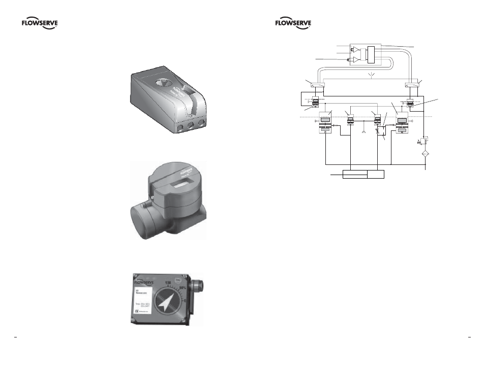
4 Variants
Pulsair III 270° (W)
A Pulsair III for up to 270° extended travel
range is available. It features all benefi ts and
options similar to the standard Pulsair III.
Communication with HART is possible.
Pulsair III Intrinsically Safe
The Pulsair III is available in an intrinsically
safe version for installation in hazardous
areas. It features the same easy-to-use user
interface for local confi guration as the Pulsair
III. Communication with HART is possible. It
features all benefi ts and options similar to the
Standard Pulsair III positioner: gauge block,
local graphic LCD display, feedback option, etc.
Pulsair III Explosion-Proof (Z)
The Pulsair III digital positioner is available
in an explosion-proof enclosure. It features
the same easy-to-use user interface for local
confi guration as the Pulsiar III. Communication
with HART is possible.
Further features are gauge ports and local
graphic LCD display.
Pulsair III Remote Mounted
The Pulsair III with remote mount is now
available. This version is suitable for
installations in severe applications, e.g.
vibration, high or low temperature, corrosive
environment, diffi cult to access installations,
etc. A fl at or dome-style indicator can be fi tted
on the feedback box installed on the actuator.
The maximum recommended distance between
the Pulsair III and remote unit is 16 ft. (5m).
Standard Housing
Weatherproof (W) and
Intrinsically Safe
“Z” Housing
Remote Mount
Control signal 4-20 mA
Potentiometer
Piezo–valve 1
Piezo–valve 2
Diaphragm
Pressure
regulator
Replaceable
Filter
Air supply
30-105 psig
(2-7 bar)
17.4 psig (1.2 bar)
V enting
Venting
H
G
Signal converter
and microprocessor
A
B
C
D
E
F
➾
C– C+
Actuator
5 Function
Double-Action Function
The control signal and the feedback potentiometer position are converted to digital
signals that are processed with a PID algorithm in the microprocessor. This provides
control signals to the two piezo-valves.
The two piezo-valves are closed in the schematic diagram above and have no effect on
the valves A and D. Air from the pressure regulator is lead through the open valve A
to the valve B, which opens. The supply pressure can now pass through valve B to the
actuator via H. The actuator then moves in the direction of the arrow. At the same time,
air from valve A keeps valve C open and allows venting of the actuator.
When both the piezo-valves open, valve A closes but valve D opens and controls valves
E and F to that the actuator moves in a direction opposite to the arrow. When only piezo-
valve 1 is open, the actuator is stationary.
Single-Action Function
Valve B is used for the supply air and valve F for venting.