Flowserve ValveSight Diagnostics User Manual
Page 58
ValveSight Diagnostics for HART User Manual FCD VSENSF0001-02-AQ 03/15
58
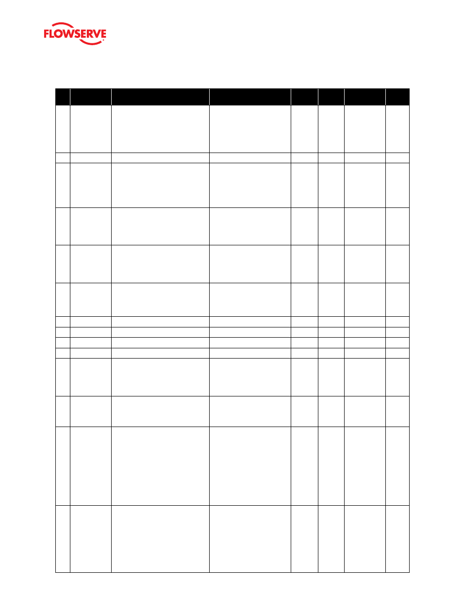
#
Indicator
Implications
Possible
Solutions
Default
Settings
Enable/
Disable
Refer to DTM
Screen
Blink
Code
62
Jog
Calibration
State
Indicates that during a job calibration,
the unit is waiting for the user to
manually adjust the valve position to
the desired 100% open position.
Use the buttons on the posi-
tioner to adjust the valve to the
desired fully open position. See
the explanation of Jog Calibrate
in the QUICK-CAL section of
main document for operation.
N/A
No
N/A
YGYR
63
N/A
64
Command
Loop Range
Too Small
Warning
Indicates that during a Command
Loop (Analog Input) Calibration, the
difference between the signal at 0%
and the signal at 100% was too small.
The system is designed to accept a
difference greater than 2 mA.
Recalibrate making sure to use
a larger difference between
command signal limits. The dif-
ference must exceed 2 mA.
N/A
No
Calibration >
Analog Input
None
65
Command
Loop 100%
Signal Out of
Range
Warning
Indicates that during Command Loop
(Analog Input) Calibration, the 100%
signal was out of range.
The system is designed to
accept a signal between ap-
proximately 3.5 mA and 22 mA.
Recalibrate making sure to set
the limits inside that range.
N/A
No
Calibration >
Analog Input
None
66
Command
Loop 0%
Signal Out of
Range Warn-
ing
Indicates that during Command Loop
(Analog Input) Calibration, the 0%
signal was out of range.
The system is designed to
accept a signal that is between
approximately 3.5 mA and 22
mA. Recalibrate making sure to
set the limits inside that range.
N/A
No
Calibration >
Analog Input
None
67
Analog Output
Range Too
Small Warn-
ing
Indicates during an Analog Output
Calibration the difference between the
milliamp signal at 0% and the milliamp
signal at 100% was too small.
Recalibrate making sure to use
a larger difference between
signal limits.
N/A
No
Calibration >
Analog Output
None
68
N/A
69
N/A
70
N/A
71
N/A
72
Pressure
Sensor Board
Present/Ab-
sent
Indicates pressure sensors are physi-
cally present in the positioner. Other-
wise the sensor option has not been
installed. The sensors are required for
many of the diagnostic features.
Pressure sensors are available
to install in the device. Contact
your Flowserve sales repre-
sentative.
N/A
No
N/A
None
73
Analog Output
Board Pres-
ent/Absent
Indicates an analog output board is
physically present in the positioner.
Otherwise the board option has not
been installed.
An analog output board is
available to install in he device.
See your Flowserve sales
representative.
N/A
No
N/A
None
74
Pressure
Control
Locked/
Inactive
Indicates that the positioner feedback
sensor is rotating clockwise to close.
This affects the fail safe position of the
valve in the event of linkage failure. In
normal configurations, a spring will
turn the sensor counter-clockwise
upon release of the feedback linkage.
Use the Valve Stability DIP
switch to toggle this mode on
or off. If high friction is set and
this indicator never comes on,
the error band limits may need
to be adjusted.
N/A
No
For DIP
switches:
Configuration
> Basic/Local
Interface
For error band
settings: Con-
figuration >
Alarms/Alerts
> Command
Deviation
None
75
Feedback
Potentiom-
eter Rotation
Reversed/
Normal
Indicates that the positioner feedback
sensor is rotating clockwise to close.
In normally configured position-
ers, a spring will turn the sensor
counter-clockwise upon release of the
feedback linkage. This affects the fail
safe position of the valve in the event
of linkage failure.
Ensure the feedback sensor
spring will lead to a proper fail
safe position. If needed, an
optional internal biasing spring
is available that can change
the direction of failure position
if the feedback linkage should
break.
N/A
No
N/A
None