Flowserve ValveSight Diagnostics User Manual
Page 54
ValveSight Diagnostics for HART User Manual FCD VSENSF0001-02-AQ 03/15
54
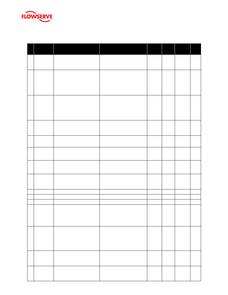
#
Indicator
Implications
Possible
Solutions
Default
Settings
Enable/
Disable
Refer to
DTM
Screen
Blink
Code
21
Friction Low
Alarm
Indicates the friction has passed
below the user set limit. The alarm
indicates a more severe condition
than the warning.
Check for a packing leak. Tighten or
replace the valve packing.
0 lbs.
Yes
Health >
Valve
Health
RRGY
22
Valve Cycles
Limit Alert
Indicates that the cycle limit has
been exceeded. The cycle counting
criterion and count limit are set by
the user to track the usage of the
valve.
Follow routine procedures for mainte-
nance when the limit is reached such
as checking the packing tightness,
and checking the linkages for wear,
misalignment, and tightness. After
maintenance, reset the cycle ac-
cumulator.
Start:
4,500,000
End at:
5,000,000
Deadband
.5%
Yes
Health>
Valve
Health
GRGG
23
Valve Travel
Limit Alert
Indicates that the total accumulated
travel limit has been exceeded. The
cycle counting criterion and count
limit are set by the user to track the
usage of the valve.
Follow routine procedures for
maintenance when the limit is
reached such as checking the packing
tightness, and checking linkages for
wear, misalignment and tightness.
After maintenance reset the travel
accumulator.
Start:
36,000,000
End:
40,000,000
Deadband
.5%
Yes
Health
> Valve
Health
GRGG
24
Stroke Cali-
bration Mode
Indicates that the calibration
sequence started either by using
the local QUICK-CAL button or by
Flowserve supplied software.
The calibration may be cancelled
by briefly pushing the QUICK-CAL
button.
N/A
Yes
Calibration
> Stroke
YGYG
25
Command
Loop Calibra-
tion Mode
Indicates the command calibra-
tion sequence started by using
Flowserve supplied software.
The command calibration can only be
cancelled by the software.
N/A
Yes
Calibration
> Analog
Input
YGYG
26
Pressure
Calibration
Mode
Indicates a pressure calibration
sequence controlled by Flowserve
supplies software.
The pressure calibration can only be
cancelled by the software.
N/A
Yes
Calibration
> Actuator YGYG
27
Analog Output
Calibration
Mode
Indicates the analog output calibra-
tion sequence started, controlled by
Flo0wserve supplied software.
The analog output calibration can
only be cancelled by the software.
N/A
Yes
Calibration
> Analog
Output
YGYG
28
Set Inner
Loop Offset
Mode
Indicates an automatic step in the
calibration process that is done with
the valve at 50% position. This must
be completed for proper calibration.
N/A
No
Calibration
> Stroke
YGYG
29
N/A
30
N/A
31
N/A
32
Circuit Board
Temperature
High Warning
Indicates the internal electronics
have exceeded the user set limit.
The maximum limit of the electron-
ics and default setting is 185
0
F (85
0
C). High temperature may limit the
life of the positioner.
Regulate the temperature of the posi-
tioner. If the temperature reading is in
error, replace the main board.
185
0
F
85
0
C
Yes
Health >
Positioner
Health
YYGG
33
Circuit Board
Temperature
Low Warning
Indicates the internal electronics
have exceeded the user set limit.
The minimum limit of the electron-
ics and the default setting is -40
0
F (-40
0
C). Low temperature may
inhibit responsiveness and accuracy.
Regulate the temperature of the posi-
tioner. If the temperature reading is in
error, replace the main board.
-40
0
F
-40
0
C
Yes
Health >
Positioner
Health
YYGG
34
Shunt Voltage
Reference
Alarm
Indicates that the circuit board is
drawing too much power.
Check internal wiring and connectors
for electrical shorts. If no shorts are
found and alarm persists, replace the
main circuit board.
N/A
Yes
Health >
Positioner
Health
RRRY
35
Piezo Voltage
Alarm
Indicates the portion or the circuit
board that drives the piezo is bad, or
piezo valve itself is bad.
If the unit is functioning and control-
ling replace the piezo, if it does not
operate replace the main circuit
board.
N/A
Yes
Health >
Positioner
Health
RRYG