Flowserve ValveSight Diagnostics User Manual
Page 57
ValveSight Diagnostics for HART User Manual FCD VSENSF0001-02-AQ 03/15
57
flowserve.com
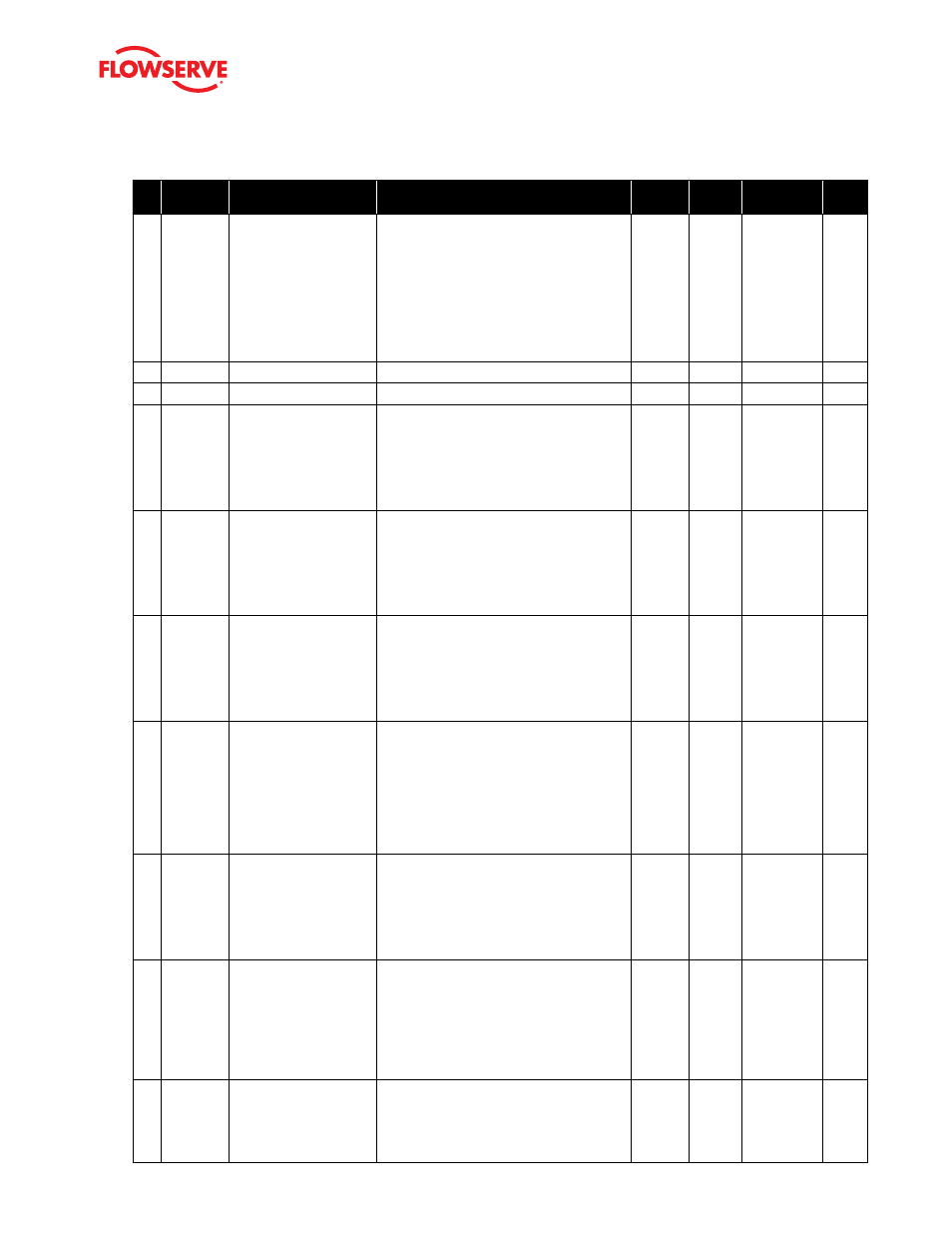
#
Indicator
Implications
Possible
Solutions
Default
Settings
Enable/
Disable
Refer to DTM
Screen
Blink
Code
53
Hall Sen-
sor Lower
Position
Alarm
Indicates the pilot relay
(spool or poppet) appears
to be unable to move in
the lower (depressur-
ized) direction and is not
responding. This could be
due to a hall sensor that is
out of calibration, a broken
piezo, stuck relay, or a wire
connection problem.
A hall sensor problem may be cleared by briefly
pushing the QUICK-CAL button, which will force
the positioner to use the parameters from the
last valid calibration. Check the internal wiring
harnesses for good connections. Check the spool
valve for sticking problems. If the positioner
still does not operate, replace the piezo, driver
module assembly,, and/or spool assembly.
N/A
Yes
N/A
RRYR
54
N/A
55
N/A
56
Feedback
Range
Too Small
Alarm
Indicates that during a cali-
bration the range of motion
of the position feedback
arm was too small for
optimum performance.
Check for loose linkages and/or adjust the
feedback pin to a position closer to the follower
arm pivot to create a larger angle of rotation
and recalibrate. Briefly pushing the QUICK-CAL
button acknowledges this condition and the posi-
tioner will operate using the current short stroke
calibration if otherwise a good calibration.
N/A
No
Calibration >
Stroke
RGGY
57
0%
Position
Out of
Range
Alarm
Indicates that during
calibration the feedback
sensor moved beyond its
range of operation at the
0% (closed) position.
Adjust the positioner mounting linkage or
feedback potentiometer to move the position
sensor back into range then restart the calibra-
tion. This error may be cleared by briefly pushing
the QUICK-CAL button, which will force the
positioner to use the parameters from the last
good calibration.
N/A
No
Calibration >
Stroke
RGGY
58
100%
Position
Out of
Range
Alarm
Indicates that during
calibration the feedback
sensor moved beyond its
range of operation at the
100% (open) position.
To correct the condition, adjust the positioner
mounting, linage or feedback potentiometer to
move the position sensor back into range then
restart the calibration. This error may be cleared
by briefly pushing the QUICK-CAL button, which
will force the positioner to use the parameters
from the last good calibration.
N/A
No
Calibration >
Stroke
RGGY
59
No Motion
Time Out
Alarm
Indicates that during
calibration there was no
motion of the actuator
based on the current stroke
time configuration.
Check linkages and air supply to make sure the
system is properly connected. If the time out
occurred because the actuator is very large then
simply retry the QUICK-CAL and the positioner
will automatically adjust for a longer actuator by
doubling the time allowed for movement. This er-
ror maybe cleared by briefly pushing the QUICK-
CAL button, which will force the positioner to use
the parameters from the last good calibration.
N/A
No
Calibration >
Stroke
RGYY
60
Non-Settle
Time Out
Alarm
Indicates that during
calibration the position
feedback sensor did not
settle.
Check for loose linkages or a loose positioner
sensor. This error may be cleared by briefly
pushing the QUICK-CAL button, which will force
the positioner to use the parameters from the last
good calibration. This error may appear on some
very small actuators during the initial calibration.
Recalibrating may clear the problem.
N/A
No
Calibration >
Stroke
RGYG
61
Inner Loop
Offset
Time Out
Alarm
Indicates that the Inner
Loop Offset value did not
set during calibration.
This could result in less
accurate positioning.
Repeat the stroke calibration to get a more
accurate ILO value. To proceed using the less
accurate ILO value, this error may be cleared by
briefly pushing the QUICK-CAL button. Lowering
the gain setting maybe help if the actuator is
unstable during the calibration. Gain settings
can be physically adjusted on the device. A lower
letter represents lower gain.
N/A
No
Calibration >
Stroke
RGGR
62
Jog
Calibration
State
Indicates that during a job
calibration, the unit is wait-
ing for the user to manually
adjust the valve position
to the desired 100% open
position.
Use the buttons on the positioner to adjust the
valve to the desired fully open position. See the
explanation of Jog Calibrate in the QUICK-CAL
section of main document for operation.
N/A
No
N/A
YGYR