3 detailed sequence of positioner operations – Flowserve 3200MD User Manual
Page 7
User Instructions - Digital Positioner 3200MD LGENIM0059-09 12/13
7
The piezo valve pressure modulator controls the air pressure under
a diaphragm by means of a piezo beam bender. The piezo beam
defl ects in response to an applied voltage from the inner-loop elec-
tronics. As the voltage to the piezo valve increases, the piezo beam
bends, closing off against a nozzle causing the pressure under
the diaphragm to increase. As the pressure under the diaphragm
increases or decreases, the spool valve moves up or down respec-
tively. The hall effect sensor transmits the position of the spool back
to the inner-loop electronics for control purposes.
4.3 Detailed Sequence
of Positioner Operations
A more detailed example explains the control function. Assume the
unit is confi gured as follows:
• Unit is in Analog command source.
• Custom characterization is disabled (therefore characterization is
Linear).
• No soft limits enabled. No MPC set.
• Valve has zero deviation with a present input signal of 12 mA.
• Loop calibration: 4 mA = 0% command, 20 mA = 100% com-
mand.
• Actuator is tubed and positioner is confi gured air-to-open.
Given these conditions, 12 mA represents a Command source of
50 percent. Custom characterization is disabled so the Command
source is passed 1:1 to the Control Command. Since zero deviation
exists, the Stem Position is also at 50 percent. With the stem at the
desired position, the spool valve will be at a middle position that bal-
ances the pressures above and below the piston in the actuator. This
is commonly called the null or balanced spool position.
Assume the input signal changes from 12 mA to 16 mA. The posi-
tioner sees this as a Command source of 75 percent. With Linear
characterization, the Control Command becomes 75 percent. Devia-
tion is the difference between Control Command and Stem Position :
Deviation = 75% - 50% = +25%, where 50 percent is the present
stem position. With this positive deviation, the control algorithm
sends a signal to move the spool up from its present position. As the
spool moves up, the supply air is applied to the bottom of the actua-
tor and air is exhausted from the top of the actuator. This new pres-
sure differential causes the stem to start moving towards the desired
position of 75 percent. As the stem moves, the Deviation begins to
decrease. The control algorithm begins to reduce the spool opening.
This process continues until the Deviation goes to zero. At this point,
the spool will be back in its null or balanced position. Stem move-
ment will stop and the desired stem position is now achieved.
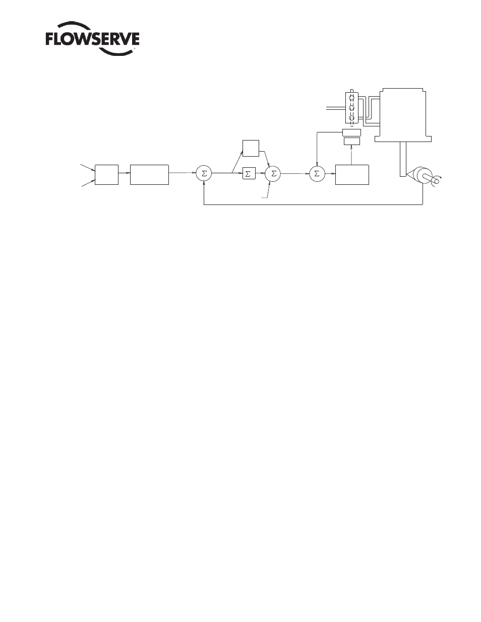
One important parameter has not been discussed to this point: Inner
loop offset. Referring to Figure 2, a number called Inner loop offset
is added to the output of the control algorithm. In order for the spool
to remain in its null or balanced position, the control algorithm must
output a non-zero spool command. This is the purpose of the Inner
loop offset. The value of this number is equivalent to the signal that
must be sent to the spool position control to bring it to a null posi-
tion with zero deviation. This parameter is important for proper con-
trol and is optimized and set automatically during stroke calibration.
Figure 2: System Positioning Algorithm
Sensor
-
+
+
+
+
Summer
Integration
I
Offset
Loop
Inner
+
-
Gmult
Pmin
Pmax
Deviation
Mode)
(Analog
mA
4-20
Mode)
(Digital
In
Command
Signal
Input
Digital
Analog
CONTROL
COMMAND
Output
D/A
Percentage
Algorithm
Control
Supply
Air
Control
Spool
Loop
Inner
ATO
Tubed
Sensor
Position
Stem
Voltage
Valve
Piezo
MPC
Soft Limits
Characterization
Linear Mode
Output
Inner-Loop