2 positioner operation – Flowserve 3200MD User Manual
Page 6
User Instructions - Digital Positioner 3200MD LGENIM0059-09 12/13
6
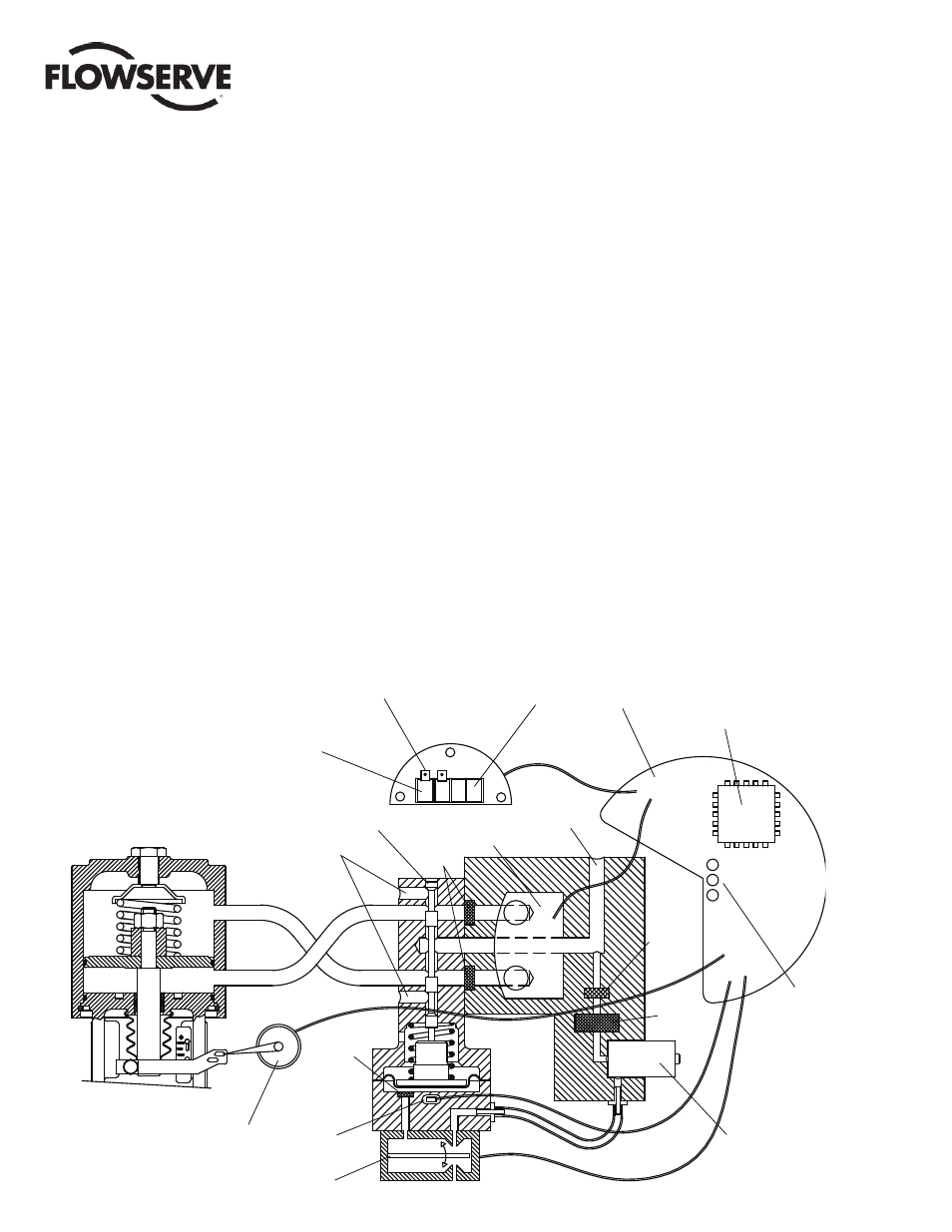
4.2 Positioner Operation
The Logix 3200MD positioner is an electric feedback instrument.
Figure 1 shows a Logix 3200MD positioner installed on a double-
acting linear actuator for air-to-open action.
The Logix 3200MD receives power from the two-wire, 4-20 mA
input signal. However, since this positioner utilizes HART com-
munications, two sources can be used for the command signal:
Analog and Digital. In Analog source, the 4-20 mA signal is used for
the command source. In Digital source, the level of the input 4-20
mA signal is ignored and a digital signal, sent via HART, is used as
the command source. The command source can be accessed with
ValveSight software, the HART 375 communicator, or other host
software.
Whether in Analog or Digital Source, 0% is always defi ned as the
valve closed position and 100% is always defi ned as the valve
open position. In Analog Source, the 4-20 mA signal is converted
to a percentage. During loop calibration, the signals corresponding
to 0% and 100% are defi ned. The input signal in percent passes
through a characterization/limits modifi er block. The positioner no
longer uses CAMs or other mechanical means to characterize the
output of the positioner. This function is done in software, which
allows for in-the-fi eld customer adjustment. The positioner has three
basic modes: Linear, Equal Percent (=%) and Custom characteriza-
tion. In Linear mode, the input signal is passed straight through to
the control algorithm in a 1:1 transfer. In Equal Percent (=%) mode,
the input signal is mapped to a standard 30:1 rangeability =% curve.
If Custom characterization is enabled, the input signal is mapped to
either a default =% output curve or a custom, user-defi ned 21-point
output curve. The custom user-defi ned 21-point output curve is
defi ned using a handheld or ValveSight software. In addition, two
user-defi ned features, Soft Limits and MPC (Minimum Position
Cutoff), may affect the fi nal input signal. The actual command being
used to position the stem, after any characterization or user limits
have been evaluated, is called the Control Command.
The Logix 3200MD uses a two-stage, stem-positioning algorithm.
The two stages consist of an inner-loop, spool control and an outer-
loop, stem position control. Referring again to Figure 1, a stem
position sensor provides a measurement of the stem movement.
The Control Command is compared against the Stem Position. If
any deviation exists, the control algorithm sends a signal to the
inner-loop control to move the spool up or down, depending upon
the deviation. The inner-loop then quickly adjusts the spool position.
The actuator pressures change and the stem begins to move. The
stem movement reduces the deviation between Control Command
and Stem Position. This process continues until the deviation goes
to zero.
The inner-loop controls the position of the spool valve by means of
a driver module. The driver module consists of a temperature-com-
pensated hall effect sensor and a piezo valve pressure modulator.
Figure 1: Logix 3200MD Digital Positioner Schematic (air-to-open confi guration)
O
O
Stem
Position
Sensor
Piezo Valve
Output 2
Output 1
Hall Effect
Sensor
Flame
Arrestor
Exhaust
Spool Valve
Flame
Arrestor
Pressure
Sensor Board
Air Supply
Analog Output Signal
Main PCB
Regulator
Filter
Flame
Arrestor
Digital Position Algorithm
LED
Display
HART Terminals
Command
Input Signal