Flowserve 3200MD User Manual
Page 15
User Instructions - Digital Positioner 3200MD LGENIM0059-09 12/13
15
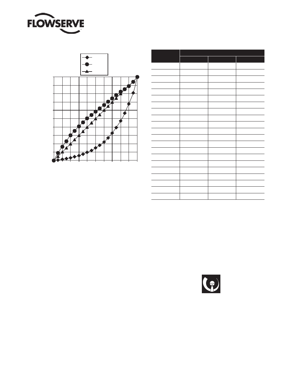
Figure 9: Default Custom Characterization
0
10 20
30 40 50
60 70
80 90 100
=%
Custom
Linear
0
10
20
30
40
50
60
70
80
90
100
% Control Command
% Command
Pos. Characterization
LinearSelect if the actuator position should be directly proportional
to the input signal. (Due to their inherent =% characteristics, this
setting give an =% Cv characteristic for most rotary valves.)
Optional Select if another characteristic is desired, which is set in
conjunction with the next switch, labeled Optional Pos. Char.
Optional Pos. Characterization
If the Pos. Characterization switch is set to optional then this switch
is active with the following options:
The =% option will characterize the actuator response to the input
signal based on a standard 30:1 equal percent rangability curve
Custom If Custom is selected, the positioner will be characterized
to a custom table that must be setup using a properly confi gured
HART 275 handheld or other host software. The Default setting for
this curve is modifi ed quick open. ( also used for a linear Cv charac-
teristic for most rotary valves)
Table VIII: Characteristic Curve Data
% Command
% Control Command
=%
Linear
Custom
0
0
0
0
5
0.62
5
8.66
10
1.35
10
16.24
15
2.22
15
23.17
20
3.25
20
30.11
25
4.47
25
35.31
30
5.91
30
40.51
35
7.63
35
45.42
40
9.66
40
50.34
45
12.07
45
54.40
50
14.92
50
58.47
55
18.31
55
62.39
60
22.32
60
66.31
65
27.08
65
70.27
70
32.71
70
74.23
75
39.40
75
78.17
80
47.32
80
82.11
85
56.71
85
85.50
90
67.84
90
88.89
95
81.03
95
94.45
100
100.00
100
100.00
Auto Tune
This switch controls whether the positioner will auto tune itself or
use preset tuning parameters.
On On enables an auto tune feature that will automatically deter-
mine the positioner gain settings based on the current position of the
selectable “Gain” switch setting and response parameters measured
during the last QUICK-CAL. The gain switch is live meaning the
settings can be adjusted at any time by changing the selectable gain
switch position. (
!
NOTE that there is a small black arrow indicating
the selection. The slot is NOT in the indicator.)
Figure 10: Adjustable GAIN Switch
A
GAIN
B
C
D
E
F
G
H
If the selectable GAIN switch is set to “D”, “C”, or “B”, with the auto
tune switch on, progressively lower gain settings will be used based
on response parameters measured during the last QUICK-CAL.
If the adjustable GAIN selector switch is set to “F”, “G”, or “H” with
the auto tune switch on, progressively higher gain settings will be
calculated and used based on response parameters measured during
the last QUICK-CAL.
If the selectable GAIN switch is set to “A” the tuning will not be
modifi ed with a QUICK-CAL. Use this setting if custom tuning will
be done using a handheld or other Flowserve software.