2 specific features, 2 name nomenclature, Lngt-800 y1 – Flowserve LNGT User Manual
Page 13
LNGT USER INSTRUCTIONS ENGLISH 00083107 02-08
Page 13 of 48
®
The pumps feature a double volute, but some
small sizes have a single volute.
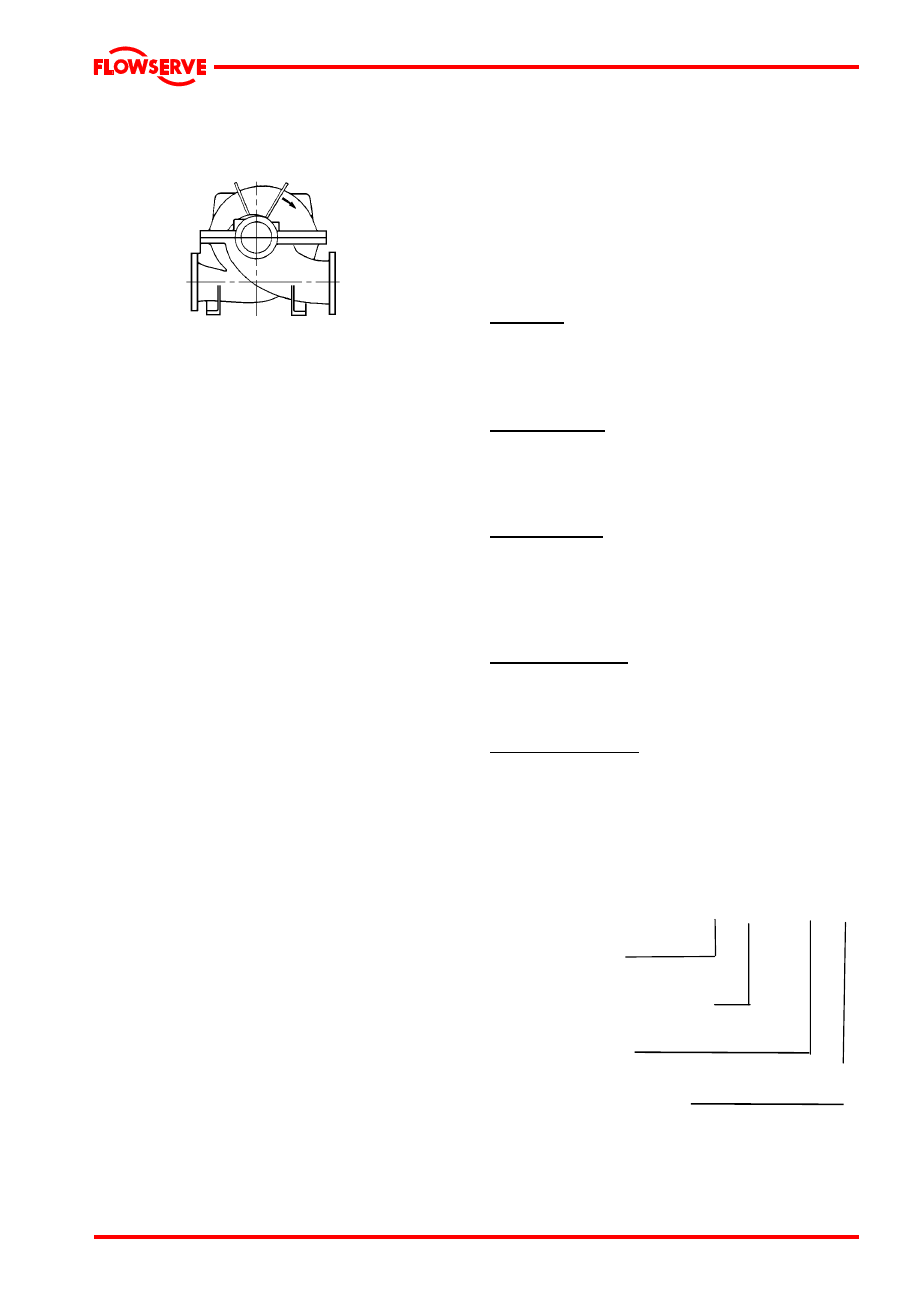
The LNGT has the following configuration:
LNGT horizontal suction and discharge nozzles [inline]
3.1.2 Specific features
The pump casing is axially split. The suction and
delivery nozzles are integral with the pump
casing bottom half and they are in line regarding
the horizontal centerline.
The two pump casing halves are assembled by
means of studs and nuts. Dismantling the pump
casing upper half allows quick inspection of the
pump internals, without it being necessary to
disturb the suction and delivery piping.
The rotor assembly can be easily removed.
Removal of pump casing and bearing housing
upper halves. If necessary use the jack screws.
Removal rotor assembly is now possible.
Reassembling of upper halves by means of
dowel pins. No realignment is needed.
The stuffing box chambers are part of the pump
casing.
In standard configuration, the pump has gland
packing rings with a lantern ring. Local to the
lantern rings, the stuffing box chambers have a
connection for flushing, in case needed. Single
mechanical seals are also available.
The space between pump casing and bearing
housing is designed in such a way, that the
packing rings can be replaced without it being
necessary to dismantle the pump. With various
pump sizes, the casing is of the double-volute
type in order to reduce radial force on the
impeller and consequently the shaft deflection.
The pump shaft is supported on either side of the
impeller by roller bearings or journal bearings
situated outside the pump casing. The bearings
are grease lubricated. Re-lubrication is possible
through the grease nipple in the bearing cover.
All pump sizes can also be provided with oil-bath
lubricated bearings. The bearing housings are
standard sealed with a V-ring (Labyrinth ring)
together with a retaining and/or thrower.
Bearing isolators are optional.
Sleeves local to the stuffing boxes protect the
pump shaft from effects of the pumped medium
and from wear local to the packing rings. On
either side of the impeller, replaceable case wear
rings are fitted to protect the pump casing. It is
also possible to provide the impeller with impeller
wear rings. The impeller wear rings are locked
with set screws to prevent co-rotation. The casing
wear rings are locked with dowel pin in the lower
half casing to prevent co-rotation.
Efficiency
The impeller and pump casings were designed,
using advanced techniques and extensive model
testing, which ensures optimum efficiency, thus
reducing the energy consumption.
Inlet conditions
Optimum design of the double-suction impeller
and optimum, elaborate test base, shaping of the
suction boxes provide the possibility of working at
low NPSH values.
Vibration/noise
The impeller is dynamically balanced, so the
pump amply satisfies maximum vibration levels
e.g. as demanded in standard VDI 2056. The
generously sized suction boxes also add to a low
noise level.
Interchange ability
The well-thought-out design ensures optimum
interchange ability of parts with those of other
sizes in the LNGT range.
Direction of rotation
The pumps are suited for both clockwise and
counter-clockwise rotation.
3.2 Name nomenclature
The pump size will be engraved on the
nameplate typically as below:
500-LNGT-800
Y1
Nominal discharge
branch size.
Configuration – see 3.1 above.
Nominal maximum
impeller diameter.
Hydraulic indentification for
impeller design
The typical nomenclature above is the general
guide to the LNGT configuration description.