Flowserve KW941 User Manual
Page 8
KW941 Pump Power Monitor USER INSTRUCTIONS ENGLISH 71569285 02-12
Page 8 of 24
flowserve.com
4 INSTALLATION
Dangerous voltages are present in
motor control panels/circuits. Make sure power is off
and locked out during installation.
INSTALLATION MUST BE PERFORMED BY
QUALIFIED PERSONNEL!
The KW941 Pump Power Monitor and its
current sensing toroid must not be installed in a
potentially explosive atmosphere.
It is important to be aware of the EUROPEAN
DIRECTIVE on electromagnetic compatibility when
wiring up and installing equipment on site. Attention
must be paid to ensure that the techniques used
during wiring/installation do not increase
electromagnetic emissions or decrease the
electromagnetic immunity of the equipment, wiring or
any connected devices. If in any doubt, contact
Flowserve for advice.
The Flowserve KW941 Pump Power
Monitor has a CE Mark approval for EMC and Low
Voltage Directive Compliance.
4.1 Location
The KW941 Display/Control module can be mounted
on the outside of the motor starter panel or a nearby
wall or structure. Use the four corner mounting screw
holes located below the see - through front cover
screws. Refer to Figure 4.1 for mounting dimensions.
The KW941 Display/Control module can be located
up to 30.5 m (100 ft.) from the motor lead that must
run through the current sensor (toroid). This is the
length limit for extending the toroid leads.
Figure 4.1
4.2 Electrical connections
Connections are made in the wiring compartment,
accessible by removing the separate cover plate on
the lower portion of the KW941. Loosen the two
thumbscrews to remove the cover plate (see Figure
4.2).
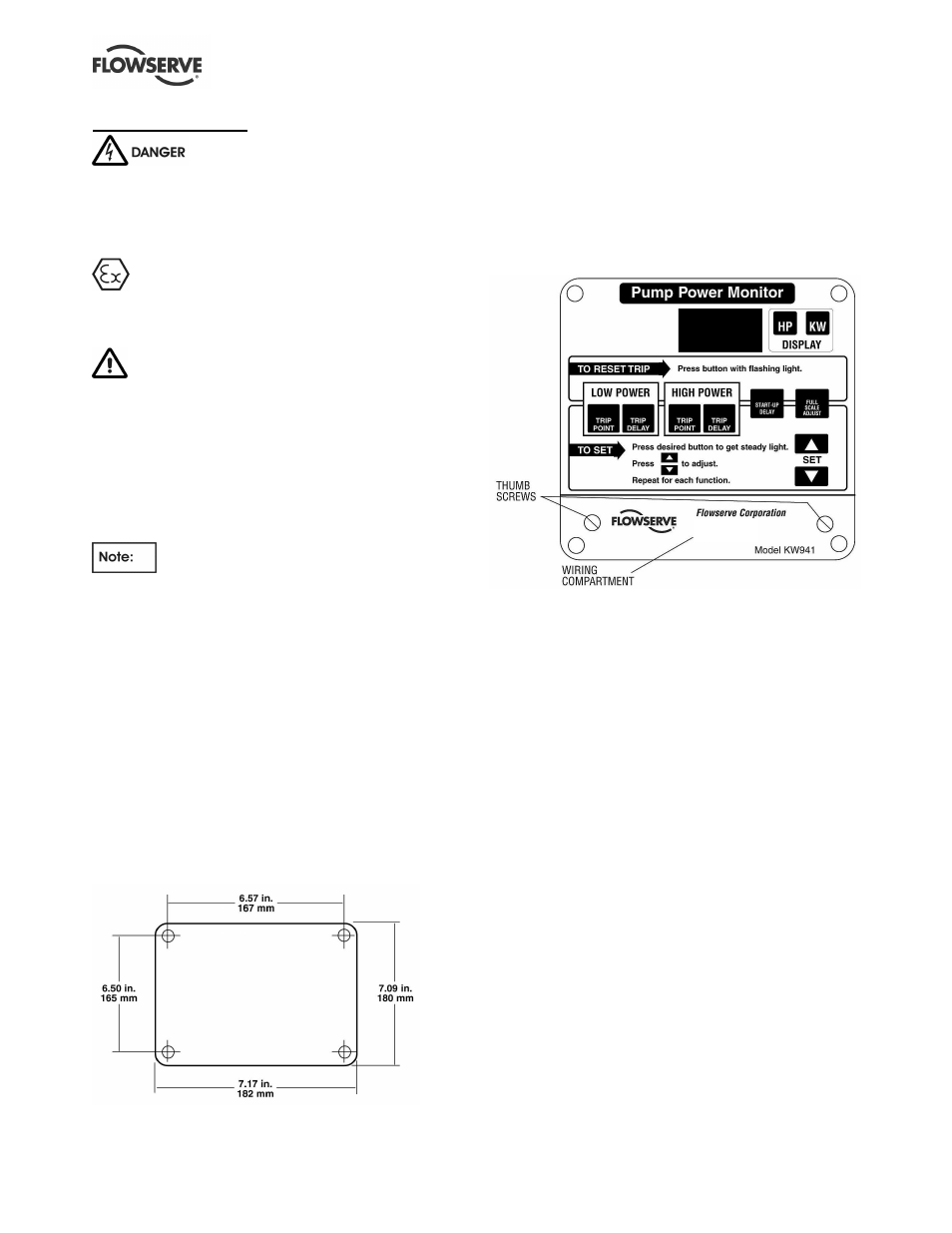
Figure 4.2
Entry for wiring/conduit is made by drilling, sawing or
punching the required hole(s) into the wiring
compartment area. Use caution when making access
holes to prevent damage to the internal components.
The following information is required for installation:
1)
Motor Nameplate Full Load Power
2)
Motor Nameplate Voltage and Hertz (Hz)
3)
Control Volts (110 or 220/240 VAC) from
transformer between motor power phases.
4)
Motor efficiency.
Record this information on the worksheet provided in
Section 8 of this manual.
4.2.1 Control Voltage
Refer to the product identification label on the outside
of the KW941 enclosure for the selected factory
preset VAC and HZ options (110/120 or 220/240
VAC, 50 or 60 HZ).