Vfsp fsp × × = 4 1 2, Vfsp fsp × × = 2 1 2 – Flowserve KW941 User Manual
Page 11
KW941 Pump Power Monitor USER INSTRUCTIONS ENGLISH 71569285 02-12
Page 11 of 24
flowserve.com
5)
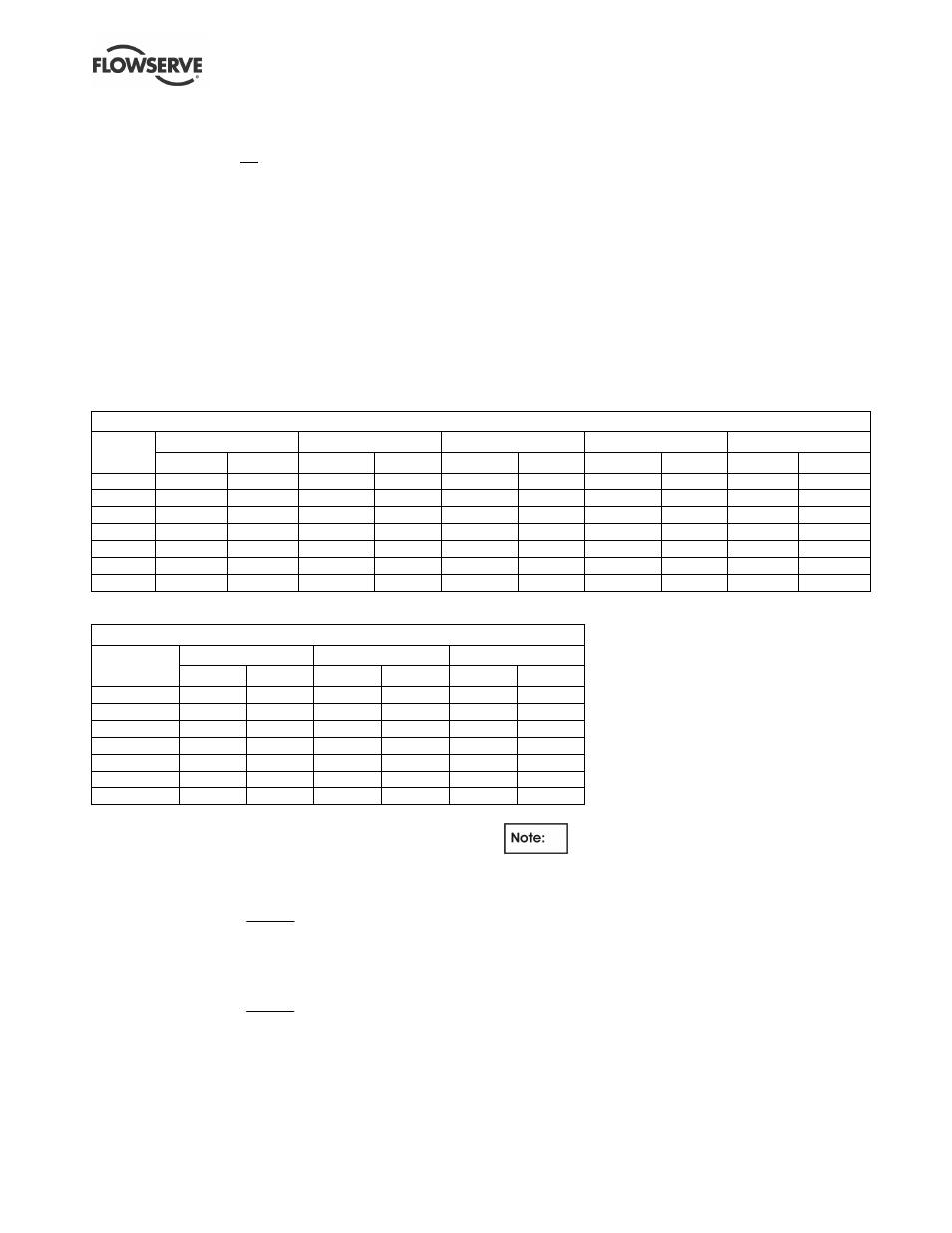
Determine the number of "turns" required by the
motor power lead through the toroid inner
diameter. Read up the table column from the
selected Full Scale Power (FS) found in step 3.
The number of turns shown in that column
header is the required number of passes the
motor power lead must make through the current
sensing toroid. Record the number of turns on
the installation and configuration worksheet in
Section 8 of this manual.
6)
Loop the motor power lead the required number
of turns through the toroid. THIS LEAD MUST
NOT BE EITHER OF THE LEADS USED FOR
THE CONTROL VOLTAGE TRANSFORMER.
Turns are counted by the number of times the
motor lead passes through the toroid center.
See Figure 4.3 for an example of one turn
through the current sensing toroid. If the motor
power lead is too large to obtain the required
number of turns, select the next larger KW941
Full Scale Power (FS) and its corresponding
number of turns. The smallest possible FS at
the required motor voltage will give best results.
7)
Connect the two leads coming from the current
sensing toroid to the KW941 TS1 (# 14 and #
15) as shown in Figure 4.3 and described in
Table 4.1. If extension leads are needed, use 24
AWG or larger wire up to 30.5 m (100 ft.) long.
Table 4.2
KW941 Full Scale Power "FS" (Jp5 set to X10 Range)
Motor
Power @ 1 turn
Power @ 2 turns
Power @ 3 Turns
Power @ 4 turns
Power @ 5 Turns
Volts
KW
HP
KW
HP
KW
HP
KW
HP
KW
HP
575
14.0
18.8
7.0
9.4
4.7
6.3
3.5
4.7
2.8
3.8
460
11.2
15.0
5.6
7.5
3.7
5.0
2.8
3.8
2.2
3.0
415
10.0
13.5
5.0
6.8
3.4
4.5
2.5
3.4
2.0
2.7
400
9.7
13.0
4.8
6.5
3.2
4.3
2.5
3.3
1.9
2.6
380
9.2
12.4
4.6
6.2
3.0
4.1
2.3
3.1
1.8
2.5
230
5.6
7.5
2.8
3.8
1.8
2.5
1.4
1.9
1.1
1.5
208
5.0
6.8
2.5
3.4
1.7
2.3
1.3
1.7
1.0
1.4
Table 4.3
KW941 Full Scale Power "FS" (Jp5 set to X1 Range -- Default)
Motor
Power @ 1 turn
Power @ 2 turns
Power @ 3 turns
Volts
KW
HP
KW
HP
KW
HP
575
140
188
69.9
93.8
46.6
62.5
460
112
150
55.9
75.0
37.3
50.0
415
101
135
50.4
67.7
33.6
45.1
400
96.9
130
48.6
65.2
32.4
43.5
380
92.5
124
46.2
62.0
30.8
41.3
230
55.9
75.0
27.9
37.5
18.6
25.0
208
50.5
67.8
25.3
33.9
16.8
22.6
For motor voltages not listed in Table 4.2 or 4.3,
calculate Full Scale Power as follows:
a)
For 110 VAC KW941 models
C
M
V
V
FSP
FSP
×
×
=
4
1
2
b)
For 220/240 VAC KW941 models
C
M
V
V
FSP
FSP
×
×
=
2
1
2
FSP1 = FS Power @ 460 VAC from Table 4.2 or
4.3
V
M
= motor voltage
V
C
= control voltage (110 or 220/240 VAC)
Control voltage is the voltage to the
KW941 VAC terminals (# 2 and # 3). This voltage
normally is the output voltage of the control
transformer in the motor starter and must be
110/115/120 or 220/230/240 VAC.
For applications with motor nameplates above 150
HP (112 KW) @ 460 VAC, if the motor lead does
not fit through the supplied current sensor, or if
custom full scale settings are desired, contact your
nearest Flowserve sales representative or
distributor.