Flowserve KW941 User Manual
Page 12
KW941 Pump Power Monitor USER INSTRUCTIONS ENGLISH 71569285 02-12
Page 12 of 24
flowserve.com
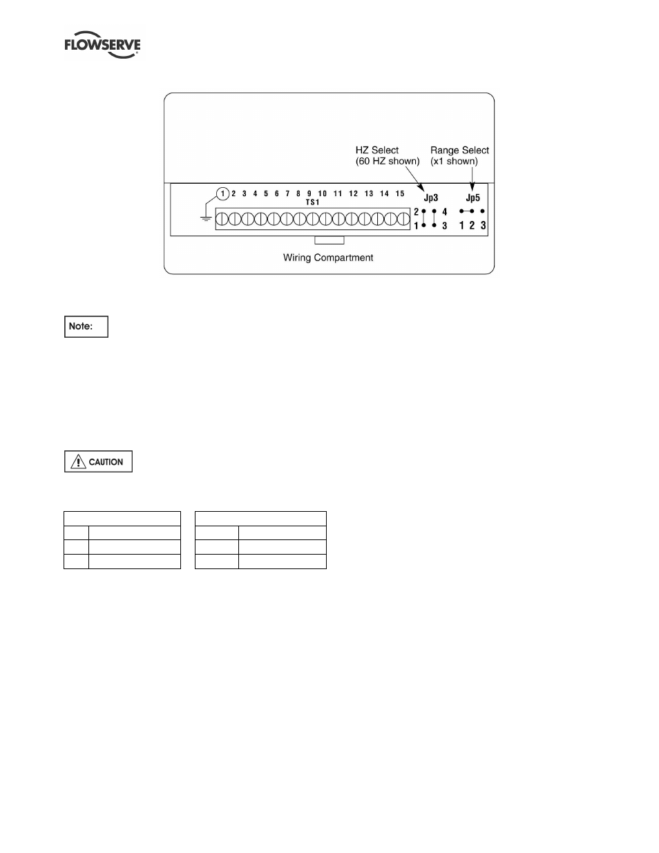
Figure 4.5
4.2.3 Jumper Settings
By default, Jumper Jp5 connections are
pins # 1 to # 2 (see Figure 4.5 and Table 4.4) which
is the “X1” range. This range is used for motors over
11.2 KW (15 HP).
For smaller motors, the jumper Jp5 may need to be
moved to pins # 2 and # 3, which is the “X10” range.
Review Tables 4.2 and 4.3 for setting the ranges for
a given Full Scale Power (FS).
Never move jumpers when power is
on!
Table 4.4
Hz Selection (Jp3)
Range Select (Jp5)
Hz Connect Pins
Range Connect Pins
50 3 to 4
X1
1 to 2 (Default)
60 1 to 2 and 3 to 4
X10
2 to 3
4.2.4 Alarm Relays
Use of a surge suppressor is recommended when
switching highly inductive loads such as a magnetic
motor starter coil.
In case of an alarm condition, alarm relay contacts
can be connected into the pump start/stop control
circuit in order to shut down the pump. Refer to
Figure 4.3 and Table 4.1 for alarm relay connections.
Relays are shown powered up, not tripped. The
relays may also be used for audible or visual alarms.
4.2.5 4-20 Milliamp Output
The output provides 4-20 milliamps proportional to
the KW941 full scale power. An external load of up to
600 Ohms can provide remote indication or input to
another device. The load is connected across TS1 #
12 (4-20 mA +) and TS1 # 13 (4-20 mA -) as
identified in Figure 4.3.