Flowserve APKD User Manual
Page 21
APKD DOUBLE-CASE, DOUBLE-SUCTION USER INSTRUCTIONS 26999903 07-13
Page 21 of 55
flowserve.com
4.1.5.3
Installation of non-adjustable flanged
coupling WNA
Follow procedure from (a) thru (e) as listed in section
4.1.5.1.
f) Install one set of split thrust rings [312A] in to the
circular keyway in pump shaft. Pull up the pump
half of the coupling [44] over the split keys.
g) Slide driver half coupling [42] onto driver shaft in
the same manner as the pump half of the
coupling.
h) Set the spacer ring [314] between the two halves
of the coupling together. Tighten all cap screws
[364] evenly to the bolt torques as listed in
4.1.5.1 under item (m).
i)
Proceed with the driver installation.
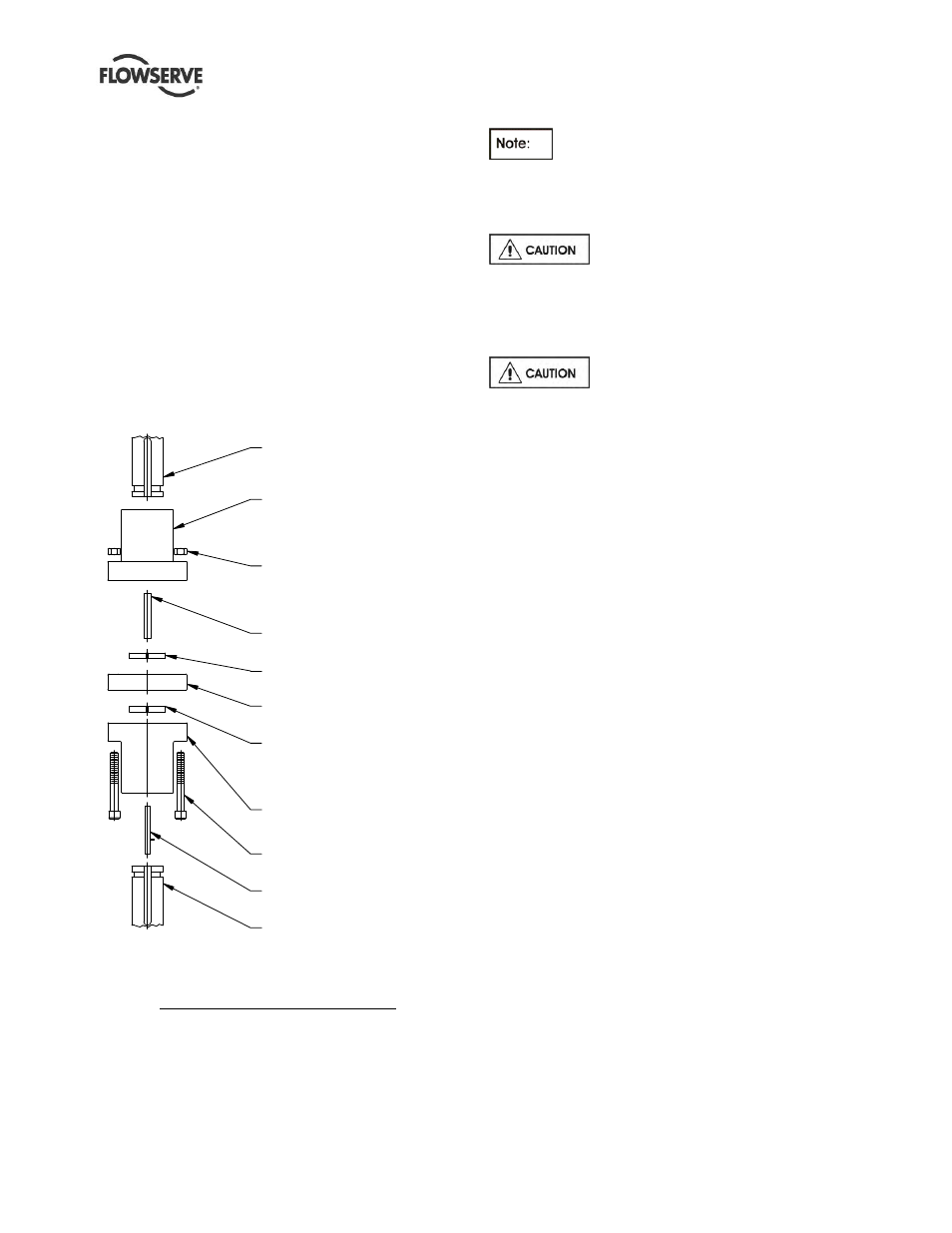
Figure 4.3
MOTOR SHAFT
(42) DRIVER COUPLING
(363) HEX NUT
(46A) DRIVE KEY
(312A) SPLIT THRUST
(314) SPACER RING
(312A) SPLIT THRUST
(44) DRIVEN COUPLING
(364) CAP SCREW
(46) KEY ASSEMBLY
(12A) TOP SHAFT
HALF
RING
RING
HALF
TYPE-WNA COUPLING DETAILS
4.1.6 Installation
of
drivers
Drivers will come with solid shaft as
specified on the order/contract.
Choose the correct installation procedure from the
following paragraphs.
Reverse rotation with the pump shaft
connected can cause extensive damage to the pump.
Always check rotation before connecting driver to
pump.
4.1.6.1
Installation of solid shaft driver
When lowering the motor and driver
half of coupling onto pump, do not let pump half of
the coupling touch the driver half of the coupling.
Before bumping motor make sure coupling halves are
not touching and that the driver can rotate freely,
without rotating the pump
Driver half coupling must be in proper position so the
circular key will not come out.
a) Clean driver mounting flange on discharge head
and check for burrs or nicks on the register and
mounting face. Oil lightly.
b) Center motor over pump and rotate to align
mounting holes. Rotate junction box into desired
position.
c) Lower driver carefully into place making certain
that the female register on the driver mates over
the male register on the pump.
d) Bolt driver to discharge head.
e) Check driver manufacturer's instructions for
special instructions including lubrication
instructions and follow all "startup" instructions.
f)
Drivers should be checked for rotation at this time.
Make electrical connections "bump" motor
(momentarily start, then stop) to check rotation.
DRIVER MUST ROTATE
COUNTERCLOCKWISE when looking down at
top end of motor. To change the direction of
rotation on a three-phase motor, interchange any
two line leads. To change direction of rotation on
a two-phase motor, interchange the leads of either
phase.
g) See impeller adjustment instructions (section 5.3)
before bolting the pump and driver half of the
coupling together.