Delta Electronics S24SA User Manual
Page 8
DS_S24SA1R812_05092006
[ ]
ΚΩ
−
∆
=
−
104
%
Vo
up
Rtrim
−
∆
+
1089
%)
100
(
8
.
23
Vo
Ex. When trim-up +10% (1.8V X 1.1 = 1.98V)
[ ]
ΚΩ
=
−
=
−
9
.
48
104
10
up
Rtrim
−
+
1089
)
10
100
(
8
.
23
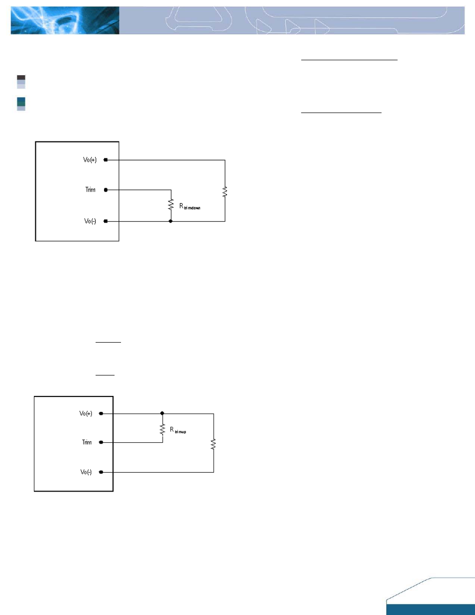
utput Voltage Adjustment (TRIM)
o increase or decrease the output voltage set point, the
Care should be taken to ensure that the maximum
output power of the module remains at or below the
maximum rated power.
FEATURES DESCRIPTIONS (CON.)
O
T
modules may be connected with an external resistor
between the TRIM pin and either the Vo+ or Vo -. The
TRIM pin should be left open if this feature is not used.
Figure 15:
Circuit configuration for trim-down (decrease output
the external resistor is connected between the TRIM
voltage)
If
and Vo- pins, the output voltage set point decreases.
The external resistor value required to obtain a
percentage of output voltage change △Vo% is defined
as:
[ ]
ΚΩ
−
∆
=
−
104
%
Vo
down
1089
Ex. When trim-down –10% (1.8V X 0.9 = 1.62V)
Rtrim
[ ]
ΚΩ
9
.
4
104
10
down
Rtrim
=
−
=
−
1089
Figure 16:
Circuit configuration for trim-up (increase output
the external resistor is connected between the TRIM
voltage)
If
and Vo+ pins, the output voltage set point increases.
The external resistor value required to obtain a
percentage output voltage change △Vo% is defined as:
8