Delta Electronics CME-COP01 User Manual
Instruction sheet, Warning, Introduction
http://www.delta.com.tw/industrialautomation/
5011648700-MPE0
2006-09-21
CANopen Network Adapter
Instruction Sheet
Warning
3
This instruction sheet only provides descriptions on electricalspecifications, general specifications, installation and
wiring and is only an introductory guide to CME-COP01. For more informaion on CANopen protocol, please refer to
relevant literature.
3
CME-COP01 is an OPEN TYPE controller and therefore should be installed in an enclosure free of airborn dust,
humidity, electric shock and vibration. The enclosure should protect non-maintenance staff from operating the device
(e.g. key or specific tools are required to open the enclosure) in case danger and damage on the device may occur.
3
CME-COP01 is for controlling the machine and equipment in operation. In order not to damange it, please allow only
qualified staff who is familiar with the structure and operation of it to intall, operate, wire and maintain it.
3
Please read this instruction carefully and follow this instruction to operation the device in order to prevent damages on
the device or injuries to staff.
3
DO NOT connect input AC power supply to any of the input/output terminals; otherwise serious damage may occur.
Check all the wiring again before switching on the power and DO NOT touch any terminal when the power is switched
on.
X
Introduction
1.1 Model
Explanation
Thank you for choosing Delta CME-COP01 CANopen communication module. CME-COP01 is specifically for
connecting to CANopen communication module of Delta VFD-E AC motor drive.
Functions of CME-COP01:
Supports Process Data Objects (PDO) Protocol
Supports Special Object Protocols (SOP)
Supports Service Data Object (SDO) Protocol
Supports Network Management (NMT) Protocol
Nameplate Explanation
CMECOP01T6160001
MADE IN XXXXXX
MODEL:CME-COP01
USED ON:VFD-E SERIES
VERSION:XX.XX
Model name
Firmware version
Barcode & series No.
Serial No. Explanation
Production series
Production week
Production year (2006)
Production plant (Taoyuan)
Serial number of version
Production Model
COP01 00 T 6 16 0001
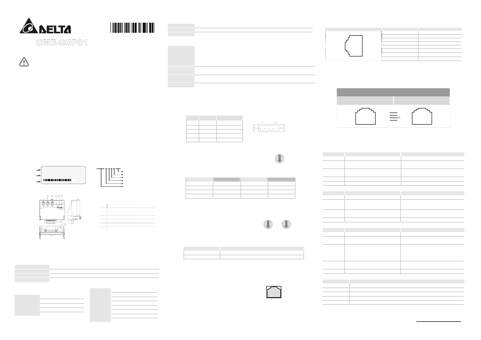
1.2 Product
Profile
1
2
7
6
3
4
5
Unit: mm
c
COM port
d
CANopen connection port
e
RUN indicator
f
ERROR indicator
g
SP (Scan Port) indicator
h
Baud rate switch
i
Address switch
Y
Specifications
CANopen Connection
Interface Pluggable
connector
(5.08mm)
Transmission method
CAN
Transmission cable
2-wire twisted shielded cable
Electrical isolation
500V DC
Communication
Process Data Objects (PDO)
Service Data Object (SDO)
Synchronization (SYNC)
Emergency (EMCY)
Message type
Network Management (NMT)
10 Kbps
20 Kbps
50 Kbps
125 Kbps
250 Kbps
500 Kbps
800 Kbps
Baud rate
1 Mbps
Product code
Delta VFD-E AC motor drive 22
Device type
402
Vendor ID
477
Environmental Specifications
Noise Immunity
ESD(IEC 61131-2, IEC 61000-4-2): 8KV Air Discharge
EFT(IEC 61131-2, IEC 61000-4-4): Power Line: 2KV, Digital I/O: 1KV,
Analog & Communication I/O: 1KV
Damped-Oscillatory Wave: Power Line: 1KV, Digital I/O: 1KV
RS(IEC 61131-2, IEC 61000-4-3): 26MHz ~ 1GHz, 10V/m
Environment
Operation: 0°C ~ 55°C (Temperature), 50 ~ 95% (Humidity), Pollution degree 2;
Storage: -40°C ~ 70°C (Temperature), 5 ~ 95% (Humidity)
Vibration / Shock
Resistance
Standard: IEC1131-2, IEC 68-2-6(TEST Fc/IEC1131-2 & IEC 68-2-27 (TEST Ea)
Certifications
Standard: IEC 61131-2,UL508
Z
Components
3.1 Pin Definition on CANopen Connection Port
To connect with CANopen, use the connector enclosed with CME-COP01 or any connectors you can buy in the
store for wiring.
Pin
Signal
Content
1 CAN_GND
Ground / 0 V / V-
2 CAN_L
Signal-
3 SHIELD
Shield
4 CAN_H Signal+
5 - Reserved
1 2 3 4 5
3.2 Baud Rate Setting
Rotary switch (BR) sets up the communication speed on
CANopen network in hex. Setup range: 0 ~ 7 (8 ~F are
forbidden)
01
2
3
4
5
6
7 8 9 A
B
C
D
EF
BR
Example: If you need to set up the communication speed of CME-COP01 as 500K, simply switch BR to “5”
BR Value
Baud rate
BR Value
Baud rate
0 10K 4 250K
1 20K 5 500K
2 50K 6 800K
3 125K 7 1M
L
The changed communication speed of CANopen is only valid when CME-COP01 is re-powered. When CME-COP01 is
operating, changing the set value of communication speed is invalid.
3.3 MAC
ID
Setting
Rotary switches (ID_L and ID_H) set up the
Node-ID on
CANopen network in hex. Setup range: 00 ~ 7F (80 ~FF
are forbidden)
01
2
3
4
5
6
7 8 9 A
B
C
D
EF
01
2
3
4
5
6
7 8 9 A
B
C
D
EF
ID_H
ID_L
Example: If you need to set up the communication address of CME-COP01 as 26(1AH), simply switch ID_H to
“1” and ID_L to “A”.
Switch Setting
Content
0 … 7F
Valid CANopen MAC ID setting
Other
Invalid CANopen MAC ID setting
L
The changed values on ID_H and ID_L are only valid when CME-COP01 is re-powered. When CME-COP01 is
operating, changing the address is invalid.
3.4 CME-COP01
Connector
The communication port of CME-COP01 is used for
connecting with Delta VFD-E AC motor drive.
PORT
3.4.1 COM PORT
Port Pin Definition
PORT Sketch
Terminal No.
Description
1 N.C.
2 N.C.
3 N.C.
4 DATA+
5 DATA-
6 GND
7 V+
1
2
3
4
5
6
7
8
8 N.C.
L
The communication port supports RS-485/Modbus communication only.
[
Connecting CME-COP01 with VFD-E
When CME-COP01 communicates with VFD-E through PORT, the power of CME-COP01 is supplied by VFD-E.
See the figure below for the wiring of connection.
RS-485 Communication
(Using standard cable with RJ-45 connectors at its two ends is suggested)
CME-COP01
RJ-45 (RS-485)
VFD-E
RJ-45 (RS-485)
8 7 6 5 4 3 2 1
8 7 6 5 4 3 2 1
DATA-
DATA+
DATA-
DATA+
(5)
(4)
(5)
V+ (7)
GND (6)
(3) GND
(2) V+
\
LED Indicator Explanation & Troubleshooting
There are 3 LED indicators, RUN, ERROR and SP, on CME-COP01 to indicate the communication status of
CME-COP01.
5.1 RUN LED
LED Status
State
Indication
OFF
No power
No power on CME-COP01 card
Single Flash
(Green)
STOPPED
CME-COP01 is in STOPPED state
Blinking
(Green)
PRE-OPERATIONAL
CME-COP01 is in the PRE-OPERATIONAL state
Green ON
OPERATIONAL
CME-COP01 is in the OPERATIONAL state
Red ON
Configuration error
Node-ID or Baud rate setting error
5.2 ERROR LED
LED Status
State
Indication
OFF
No error
CME-COP01 is working condition
Single Flash
(Red)
Warning limit reached
At least one of error counter of the CANopen
controller has reached or exceeded the warning
level (too many error frames)
Double Flash
(Red)
Error control event
A guard event or heartbeat event has occurred
Red ON
Bus-off
The CANopen controller is bus-off
5.3 SP LED
LED Status
State
Indication
OFF
No Power
No power on CME-COP01 card
LED Blinking
(Red)
CRC check error
Check your communication setting in VFD-E
drives (19200,<8,N,2>,RTU)
Red ON
Connection failure/No connection
1. Check the connection between VFD-E drive
and CME-COP01 card is correct
2. Re-wire the VFD-E connection and ensure
that the wire specification is correct
LED Blinking
(Green)
CME-COP01 returns error code
Check the PLC program, ensure the index and
sub-index is correct
Green ON
Normal
Communication is normal
5.4 LED Descriptions
State
Description
LED ON
Constantly on
LED OFF
Constantly off
LED blinking
Flash, on for 0.2s and off for 0.2s
LED single flash
On for 0.2s and off for 1s
LED double flash On for 0.2s off for 0.2s, on for 0.2s and off for 1s
The content of this instruction sheet may be revised without prior notice. Please consult our distributors or
download the most updated version at http://www.delta.com.tw/industrialautomation