Drake EH24A/EH24A ASI User Manual
Page 12
12
12 Ethernet Control Interface Configuration (Continued)
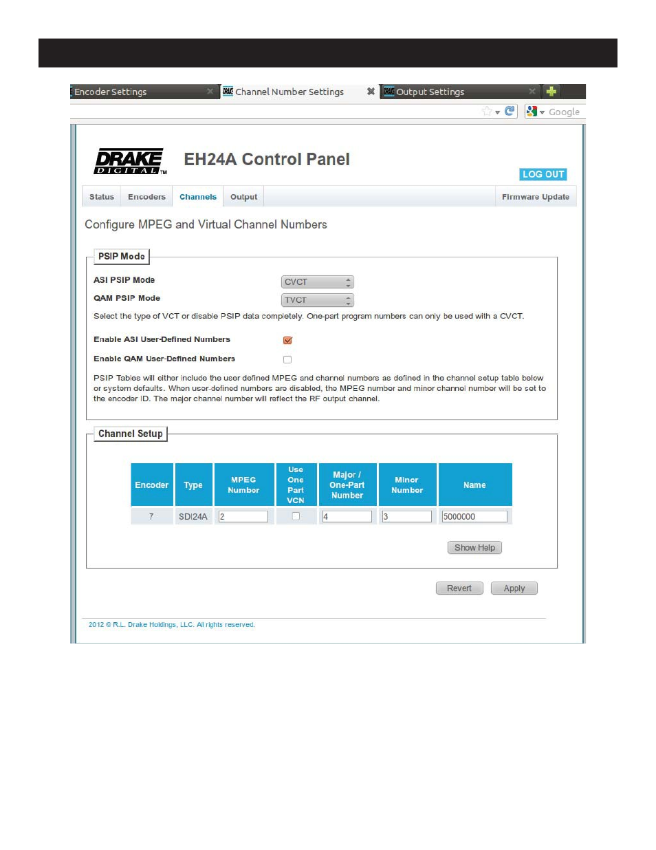
Figure 3: EH24A Channels Tab
The Channels tab provides an interface to configure the virtual channel mappings for this encoder host. If PSIP is
enabled, this page will display a screen that looks like Figure 3; for each encoder output, the MPEG program number can
be modified, along with the Major and Minor channel numbers. If one-part virtual channel numbers are desired, the PSIP
Mode must be set to CVCT and the Minor number for each channel should be set to 0.
The Output tab provides an interface to set all modulator output settings for the unit. A screenshot of this tab is shown
in Figure 4. This tab selects the DTA and EAS modes, channel bitrates, QAM settings, and the mapping from encoders to
output channels. For settings like the DTA/EAS options, more options appear as you enable the sub-systems.