DNF Controls GC-32 GPIO Controller User Manual
Page 12
Page 12 of 14
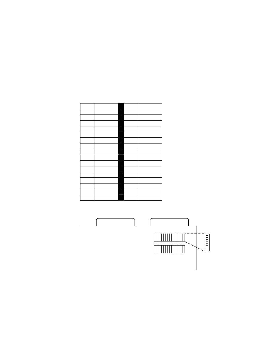
CONFIGURE GPIS FOR DRY/WET OPERATION
GPIs are set to Dry operation by default. The GPIs may be set for Wet mode
using either a Breakout Panel or using jumpers within the GC-32. To configure
the jumpers inside the GC-32:
1. Power down the GC-32 and then remove the top cover.
2. The jumpers for the GPIs are directly behind the GPI connectors, labeled
J7 through J38. Each set of jumpers for a GPI consists of 4 pins. See the
table below for which GPI corresponds to which jumpers.
3. For Dry operation, set one jumper across pins 2 and 3. Hang the second
jumper off of pin 1.
4. For Wet operation, set one jumper across pin 1 and 2. Set the second
jumper across pins 3 and 4.
5. Once all necessary changes to the jumpers have been made, replace the
top cover and power up the GC-32.
GPI Jumper
GPI Jumper
1
J7
17
J23
2
J8
18
J24
3
J9
19
J25
4
J10
20
J26
5
J11
21
J27
6
J12
22
J28
7
J13
23
J29
8
J14
24
J30
9
J15
25
J31
10
J16
26
J32
11
J17
27
J33
12
J18
28
J34
13
J19
29
J35
14
J20
30
J36
15
J21
31
J37
16
J22
32
J38
GPI Connectors
GPO Connectors
J7
J22
J23
J38
Pin 1
Pin 2
Pin 3
Pin 4