Mounting and connection – Digi-Star EZ 3200/EZ 3200V/EZ 3200V RC User Manual
Page 5
Digi-Star Model EZ3200/EZ3200V/EZ3200V RC
2. Mounting and connection
2
! copyright - 10/24/2001
2. Mounting and connection
INDICATOR MOUNTING
The indicator is easily attached to the Indicator Mounting Bracket by hooking the top over the
plate and securing the bottom with two screws and nuts (size# 10 - 24 × 5/8" or M5 × 16mm).
POWER CONNECTION
Warning!
Always disconnect the indicator power cord before “jump starting” or fast charging a battery.
Disconnect all indicator leads before welding on equipment. Failure to do so can cause surges
which will damage the scale.
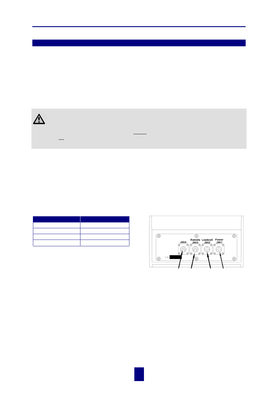
The power cable should be connected directly to a vehicle battery or regulated power supply. The
scale end of the power cable is attached to the J901 connector located on the bottom panel of the
scale.
Connect the RED wire from the power cable to +12VDC and the BLACK wire to GROUND. The
indicator is fused internally at 4 amps.
POWER CABLE CONNECTIONS INDICATOR BOTTOM PANEL
CABLE CONNECTIONS
Wire Color
Wire Function
RED
Battery (+12Vdc)
BLACK
GROUND
ORANGE
Remote Alarm Out+
BLUE
Remote Input
REMOTE ALARM CONNECTION
If a remote 12 Vdc alarm is to be used, connect
the +12Vdc side of the alarm to the power cable
ORANGE wire and the GROUND side of the
alarm to the frame (= ground).
!
The alarm output is fused for a maximum drain of 10 amps. The remote alarm connection
may also be used for motor control purposes when used with a relay.
REMOTE INPUT CONNECTION
If the remote input is to be used, connect one side of the normally open momentary switch or
relay contact to the power cable BLUE wire, and the other side to the frame or other GROUND
connection. If your power cable does not contain a blue wire and you desire to use this feature,
contact your dealer for a special cable. A process control box is available for motor control and
remote enter preset capability.
Serial
Port
Cable
(Optional)
Junction
Box
Cable
Remote
Display
Cable
(Optional)
Power
Cable