Chapter 2 – DFI KB160 User Manual
Page 26
www.dfi .com
26
Chapter 2 Hardware Installation
Chapter 2
DFI Proprietary Extension Bus
Pins
Pin Assignment
Pins
Pin Assignment
A1
GND
B1
+12V
A2
+12V
B2
+12V
A3
+12V
B3
+12V
A4
GND
B4
GND
A5
+5V
B5
SMB_CLK
A6
+5V
B6
SMB_DATA
A7
+5V
B7
GND
A8
+5V
B8
+3V3
A9
+3V3
B9
NC
A10
+3V3
B10
+3VDU
A11
RESET-
B11
PCIE_WAKE-
A12
GND
B12
PME-
A13
CLK+
B13
GND
A14
CLK-
B14
TX+
A15
GND
B15
TX-
A16
RX+
B16
GND
A17
RX-
B17
PCIECLKRQ-
A18
GND
B18
GND
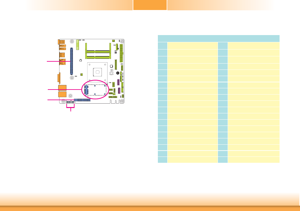
Expansion Slots
EXC Slot
The EXC interface
is used to install an EXC board for I/O expansion.
Mini PCIe Slot
The Mini PCIe socket is used to install a half size Mini PCIe card. Mini PCIe card is a small
form factor PCI card with the same signal protocol, electrical definitions, and configuration
definitions as the conventional PCI. It supports PCIe and USB signals.
PCI Express x4 Slot
Install PCI Express cards such as network cards or other cards that comply to the PCI Express
specifications into the PCI Express x4 slot.
DFI Proprietary Extension Bus
The DFI Proprietary Extension Bus gold finger is used for customized expansion (PCI or Mini
PCIe) via a riser card.
PCI Express x4
Mini PCI Express
EXC
DFI Proprietary
Extension Bus