Chapter 2 – DFI KB160 User Manual
Page 22
www.dfi .com
22
Chapter 2 Hardware Installation
Chapter 2
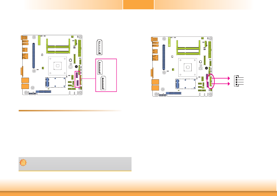
SATA (Serial ATA) Power Connectors - KB161 Series
These SATA power connectors supply power to the SATA drive. Connect one end of the pro-
vided power cable to the SATA power connector and the other end to your storage device.
SATA
Power 0
SATA
Power 1
+12V
+5V
Ground
1
Ground
4
SATA (Serial ATA) Connectors
7
RXN
GND
TXP
TXN
GND
1
RXP
GND
• 2 Serial ATA 3.0 ports
- SATA0 and SATA1 ports with data transfer rate up to 6Gb/s
- One multiplexed with mSATA (Mini PCIe) (optional)
• Integrated Advanced Host Controller Interface (AHCI) controller
The Serial ATA connectors are used to connect Serial ATA devices. Connect one end of the Se-
rial ATA data cable to a SATA connector and the other end to your Serial ATA device.
BIOS Setting
Configure the Serial ATA drives in the Advanced menu (“IDE Configuration” submenu) of the
BIOS. Refer to chapter 3 for more information.
Features
SATA 3.0 6Gb/s
(SATA port 1 provides adequate
space for SATA DOM.)
SATA 1
SATA 0
Note:
SATA port 0 will not be populated on the system board while the Mini PCIe interface
transmits the mSATA signal.