I/o connectors, Chapter 2 i/o connectors – DFI BT100 User Manual
Page 25
www.dfi .com
25
Chapter 2 Hardware Installation
Chapter 2
I/O Connectors
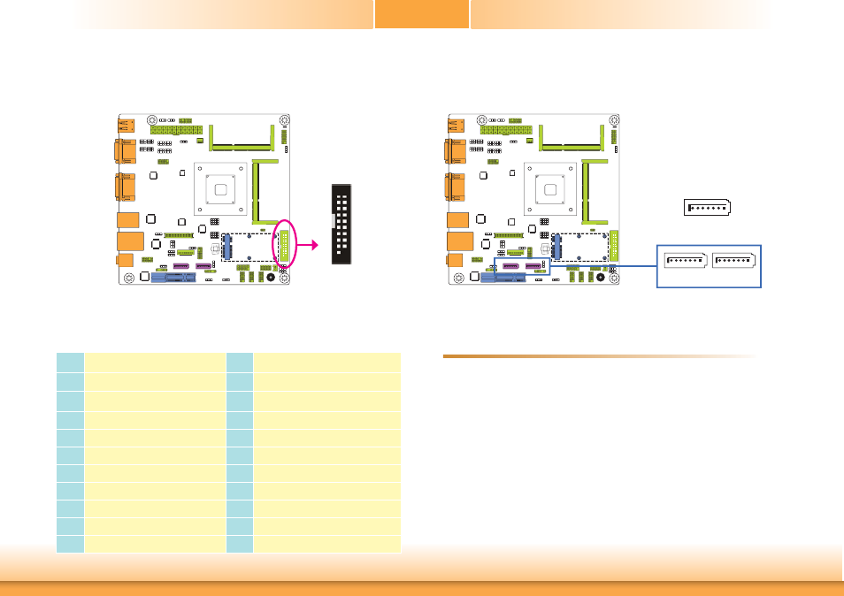
Digital I/O and/or Power Connector
The 8-bit Digital I/O connector provides powering-on function to external devices that are
connected to these connectors. The pin functions of the 8-bit digital I/O connector are listed
below.
Digital I/O Connector
Pins
Pin Assignment
Pins
Pin Assignment
1
GND
2
+12V
3
DIO7
4
+12V
5
DIO6
6
GND
7
DIO5
8
+5V
9
DIO4
10
+5V
11
DIO3
12
GND
13
DIO2
14
+5V_Standby
15
DIO1
16
+5V_Standby
17
DIO0
18
GND
19
GND
19
1
2
Digital I/O
SATA (Serial ATA) Connectors
7
RXN GND
TXP
TXN
GND
1
RXP
GND
• 2 Serial ATA 2.0 ports
- SATA 0 and SATA 1 ports with data transfer rate up to 3Gb/s
• Integrated Advanced Host Controller Interface (AHCI) controller
The Serial ATA connectors are used to connect Serial ATA devices. Connect one end of the Se-
rial ATA data cable to a SATA connector and the other end to your Serial ATA device.
BIOS Setting
Configure the Serial ATA drives in the Advanced menu (“IDE Configuration” submenu) of the
BIOS. Refer to chapter 3 for more information.
Features
SATA 1
SATA 0
SATA 2.0 3Gb/s
(SATA port 0 provides adequate
space for SATA DOM.)