Connection 4. installer commmissioning 5. using, Alarm, User mode – Delta Dore T1C-2 DIGIT User Manual
Page 2: Informed" user mode
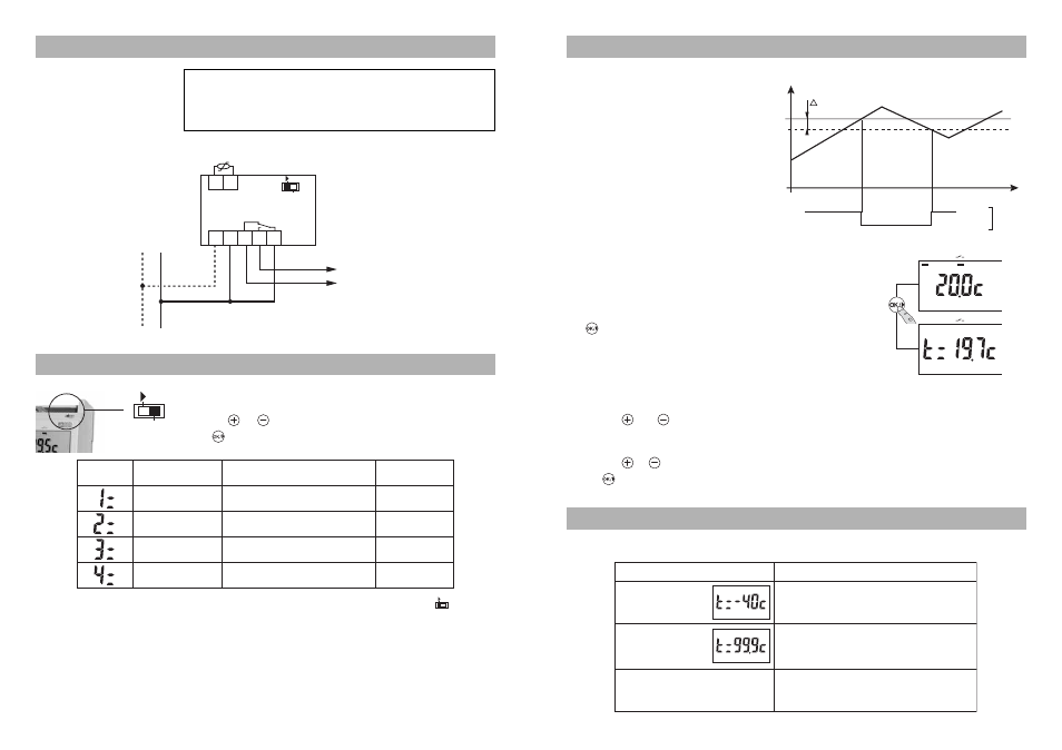
T1C-2 digit continuously compares
the setpoint temperature displayed on
the thermostat with the temperature
measured by the sensor.
When the measured temperature
exceeds the setpoint temperature,
the output switches to Off.
When the measured temperature
falls below (setpoint temperature -
Δ
t), the output switches to On.
Δ
t = Differential (set during
commissioning)
User mode
T1C-2 digit continuously displays the current setpoint
temperature.
The measured temperature can be displayed by pressing
the
button.
Note : The display can be reversed (refer to § “Installer
Commissioning”).
"Informed" user mode
To change the setpoint temperature.
Press the
and
buttons simultaneously (for approximately 5 seconds) until the
display starts flashing.
Release the buttons.
Press the
or
button to set the temperature that you want.
Press
to accept the value.
Measured
temperature (Tm)
On
Output
state
Off
T
Setpoint (Tc)
Problem
Diagnosis / Solution
The sensor is cut off
Check the sensor or its connection.
The sensor is short-circuited
Check the sensor or its connection.
There is a problem inside the thermostat
Switch off, then switch on again.
If the problem persists, contact the installer.
When the measured
temperature is
consulted, the
thermostat displays:
When the measured
temperature is
consulted, the
thermostat displays:
The temperature display is correct,
but the "Alarm" light is flashing.
1
1
Place the switch in the PROG position.
Press the
ou
buttons to display the required value.
Press
to accept and go to the next parameter.
When all the settings have been defined, the switch must be returned to the
position.
CAUTION :
If the setpoint is above 70 °C, do not program a differential of less than 1 °C.
PROG
N
L
3 4
1 2
5 6 7
Cold source
Sensor
T1C-2 Digit
Heat source
PROG
N L
230 V~
50 Hz
230 V~
5A max
PROG
Function no.
Description
Setpoint
temperature
From - 9.5 ˚C to + 90 ˚C
in 0.5 ˚C steps
+ 20˚C
Setting
Default value
Differential
From + 0.2 ˚C to + 2 ˚C
in 0.1 ˚C steps
0,2˚C
Displayed
temperature
0 = Setpoint temperature
1 = Measured temperature
0
Sensor correction
From - 2 ˚C to + 2 ˚C
in 0.5 ˚C steps 0 ˚C
0˚C
For clarity, only schematic diagrams are given here. They do not show the
protective devices and other accessories required by the standards.
- The UTE C15-100 standard and good practice must be complied with.
- Connected or adjacent appliances must not generate excessive
interference (directive 2004/108/EEC).
3. Connection
4. Installer commmissioning
5. Using
The "Alarm" warning light flashes to indicate that a fault has occurred.
6. Alarm