Delta Electronics Programmable Logic Controller DVP-SA User Manual
Warning, Introduction, Specifications
Warning
This Instruction Sheet only provides descriptions for electrical specifications, general specifications, installation &
wiring. Other detail infromation about programming and intructions is compatible with SA/SX/SC series; please see
PLC Application Manual. For more information about the optional peripherals, please see individual product
instuction shee or “DVP-PLC Application Manual: Special module”.
This is an OPEN TYPE PLC. The PLC should be kept in an enclosure away from airborne dust, humidity, electric
shock risk and vibration. Also, it is equipped with protective methods such as some special tools or keys to open the
enclosure, in order to prevent hazard to users or damage the PLC.
Do NOT connect the AC main circuit power supply to any of the input/output terminals, or it may damage the PLC.
Check all the wiring prior to power up. To prevent any electromagnetic noise, make sure the PLC is properly
grounded
. Do NOT touch terminals when power on.
Introduction
Thank you for choosing DELTA’s PLC DVP series. The DVP-SA series has a 12-points (8 input points + 4
outputs) PLC main processing unit with multiple instructions for use. It also has an 8K Steps program memory
to connect to every SA/SX/SC series extension unit, including digital I/O (Maximum 128 inpu/128 output
extension points), analog module, etc. for various applications. Its power unit is separated from the MPU for
better space utilization and easier installation.
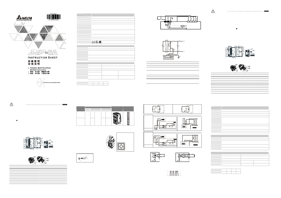
Product Profile and Outline
Unit: mm
Battery replacement: Battery replacement must be finished within 3 minutes, or the internal data of the PLC
(including the program area, RTC and latched registers) could be lost or destroyed.
1
Status indicator: POWER, RUN, ERROR, BAT.LOW
12 Extension port
2
RUN/STOP switch
13 Mounting hold of the extension unit
3
VR0: Start-up by M1178/D1178 corresponding value
14 DIN rail (35mm)
4
VR1: Start-up by M1179/D1179 corresponding value
15 Extension unit clip
5
DIN rail clip
16 COM2 (RS-485) communication port
6
I/O terminals
17 DC Power input
7
I/O point indicators
18 2 pin removable terminal (standard accessory)
8
COM1 (RS-232) (Rx) indicator
19 Power input cable (standard accessory)
9
COM2 (RS-485) (Tx) indicator
20 Battery cover
10 COM1 (RS-232) port
21 Battery socket connection
11 Nameplate
22 Battery mount
ENGLISH
Specifications
Model
Item
DVP12SA11R/T
Power supply voltage
MPU: 24V DC (-15% ~ 20%) (with DC input reverse polarity protection)
Fuse
2A / 250V AC
Power consumption
3.5W
Insulation resistance
> 5M
Ω at 500V DC (between all inputs / outputs and earth)
Noise immunity
ESD: 8KV Air Discharge
EFT: Power Line: 2KV, Digital I/O: 1KV, Analog & Communication I/O: 250V
Damped-Oscillatory Wave: Power Line: 1KV, Digital I/O: 1KV
RS: 26MHz ~ 1GHz, 10V/m
Grounding
The diameter of grounding wire cannot be smaller than the wire diameter of terminals L
and N (All DVP units should be grounded
directly to the ground pole).
Environment
Operation: 0°C ~ 55°C (temperature), 50 ~ 95% (humidity), pollution degree 2
Storage: -25°C ~ 70°C (temperature), 5 ~ 95% (humidity)
Vibration/shock resistance
Standard: IEC61131-2, IEC 68-2-6 (TEST Fc)/IEC61131-2 & IEC 68-2-27 (TEST Ea)
Weight (approx. g)
158
Certificates
Input Point Electrical Specification
Input type
DC (SINK or SOURCE)
Input current
24V DC 5mA
Off → On,
X0, X1, 18.5V DC and above
X2 ~ X7, 16.5V DC and above
Active level
On → Off,
X0 ~ X7, below 8 V DC
Response time
About 10ms (an adjustment range of 0 ~ 20ms could be selected through D1020 and D1021)
Output Point Electrical Specification
Output type
Relay-R
Transistor-T
Current specification
1.5A/1 point (5A/COM)
0.3A/1 point @ 40°C; When the output of Y0 and Y1 is high-speed
pulse, Y0 and Y1 = 30mA
Voltage specification
Below 250V AC, 30V DC
30V DC
75VA (inductive)
Maximum loading
90W (resistive)
9W/1 point
When the output of Y0 and Y1 is
high-speed pulse, Y0 and
Y1 = 0.9W (Y0 = 32KHz, Y1 =
10KHz)
Response time
About 10ms
Off
→On 20us
On
→Off 30us
Y0 and Y1 are specified points
for high-speed pulse
Battery life:
Temperature (
°C)
0
25
50
70
Life (year)
9
8
6
5
Precision of calendar timer:
At 0
°C/32°F, less than -117 seconds error per month.
At 25
°C/77°F, less than 52 seconds error per month.
At 55
°C/131°F, less than -132 seconds error per month.
Model Name & I/O Configuration
Input/Output
Input Unit
Output Unit
Model
Power
Point
Type
Point
Type
Profile
reference
I/O Configuration
DVP12SA11R
8
4
Relay
DVP12SA11T
24V DC
8
DC Sink or
Source
4
Transistor
S/S
X0
X1
X2
X3
X4
X5
X6
X7
C0
Y0
C1
C2
Y1
Y2
Y3
Installation & Wiring
4.1 PLC Mounting Arrangements and Wiring Notes
Installation of the DIN rail:
The DVP-PLC can be secured to a cabinet by using
the DIN rail that is 35mm high with a depth of 7.5mm.
When mounting the PLC on the DIN rail, be sure to
use the end bracket to stop any side-to-side motion
of the PLC, thus to reduce the chance of the wires
being pulled loose. At the bottom of the PLC is a
small retaining clip. To secure the PLC to the DIN
rail, place it onto the rail and gently push up the clip.
To remove it, pull down the retaining clip and gently
pull the PLC away from the DIN rail. As shown on the
right:
When installing the DVP series
PLC, make sure that it is
installed in an enclosure with
sufficient space (as shown
below) to its surroundings so as
to allow heat dissipation.
DV P
M P U
D
D
D
D
D > 50 mm
Wiring:
22-16AWG
<1.5mm
1. Please use 22-16AWG (1.5mm) wiring (either single or multiple core) for
I/O wiring terminals. The specification for the terminals is as shown on
the left. PLC terminal screws should be tightened to between1.95 kg-cm
(1.7 in-lbs).
2. I/O signal wires or power supply should not run through the same
multi-wire cable or conduit. Use 60/75°C copper Conductor only.
4.2 Wiring Notes
Environment
1. DO NOT store the PLC in an atmosphere that is dusty, smoky, with metallic debris or corrosive or
flammable gases.
2. DO NOT store the PLC in an environment with high temperature or high humidity.
3. DO NOT install the PLC on a shelf or on an unstable surface.
Power Input Wiring
DVP-SA series input power supply is DC input. Please take a note of listed items when operating DVP-SA
Series.
1. Please make sure the power is at terminals 24VDC and 0V (power range is 20.4 ~ 28.8V DC). When
voltage is lower than 20.4V DC, PLC will stop operating, all outputs will be Off and ERROR LED will flash
continuously.
2. If the power-cut time is less than 10ms, the PLC still operates unaffectedly. If the power-cut time is too
long or the power voltage drops, the PLC will stop operating and all the outputs will be Off. Once the
power is restored, the PLC will return to operation automatically. (There are latched auxiliary relays and
registers inside of the PLC, please be aware when programming.)
DC Input Type
24V
2A
S/S
X0
X1
X2
20.4V~28.8V
0V
DC/DC
5V
Safety Wiring
Since the PLC is used to control numerous devices, motion of either one device could affect the motion of other
devices. Therefore the breakdown of a device would consequently be detrimental to the whole auto control
system, thus the result is dangerous. Please use the recommended wiring below for the power input:
M C
MC
N
L
1
1
2
3
4
5
6
7
8
G ua r d
Lim it
MC
Power supply for AC loads
Power Circuit Protection Fuse (3A)
Power On pilot indicator
Emergency stop
The machinery must provide a quick manual method disconnecting all system power.
Circuit isolation device (System Power Disconnect)
Utilize the electromagnetic contactor and the relay to be the isolation unit of the power circuit
to prevent the possible instability of the system when the power is supplied on and off.
DVP PLC MPU (main processing unit)
Grounding
Power supply:
AC: 100 ~ 240V AC, 50/60Hz
DC: 24V DC
Input Point Wiring
The DC power is used for DC input signal.
Two types of DC wiring are used: SINK and SOURCE, defined as follows:
Sink = Current flows into the common terminal S/S
Source = Current flows out of common terminal S/S
S in kin g
S /S
X 0
Sourcing
S/ S
X0
Input Point Loop Equivalent Circuit
Wiring Loop
DC Type
(DC Signal IN)
SINK Mode
+24 V
24G
S/S
X0
24V DC
SI NK
+5 V
+ 2 4V
O V
Sink Type
X 1
X 2
S /S
X 0
24VDC
Input Point Loop Equivalent Circuit
Wiring Loop
DC Type
(DC Signal IN)
SOURCE Mode
+ 2 4V
2 4 G
S /S
X 0
24VDC
SOURCE
+ 5 V
Sou rc e Ty pe
X1
X2
S/S
X0
+24V
OV
24VD C
Output Point Wiring
Y0
RY
LED
C0
LOAD
POWER
DVP-**-**-11-R
RELAY OUTPUT
DVP-**-**-11-T
TRANSISTOR OUTPUT
LED
Y0
C0
LOAD
< 0.3A
T
R
G
1. Two types of DVP-SA Series PLC output modules: Relay or Transistor. For the electrical specification,
please refer to the function specification.
2. Please watch out the connection of common terminals while wire the outputs. For example, when wiring
DVP12SA11R, output terminal Y0 uses one common terminal C0, Y1 uses C1, and Y2~Y3 share C2, as
shown below:
C0 Y0 C1 Y1 C2 Y2 Y3
Action indication: When the output point is active, the corresponding indicator at the front panel will be on.
3. Isolated circuit: The optical coupler is used to isolate signals between PLC internal circuits and input
modules.
注意事項
本使用說明書僅提供電氣規格、功能規格、安裝配線部份說明,其它詳細之程式設計及指令與 SA/SX/SC 系列
相容,詳細說明請見 DVP-PLC 應用技術手冊【程式篇】,選購之週邊裝置詳細說明請見該產品隨機手冊或
DVP-PLC
應用技術手冊【特殊模組篇】。
本機為開放型 (OPEN TYPE) 機殼,因此使用者使用本機時,必須將之安裝於具防塵、防潮及免於電擊/衝擊
意外之外殼配線箱內。另必須具備保護措施(如:特殊之工具或鑰匙才可打開)防止非維護人員操作或意外
衝擊本體,造成危險及損壞。
交流輸入電源不可連接於輸入/出信號端,否則可能造成嚴重損壞,請在上電之前再次確認電源配線。請勿
在上電時觸摸任何端子。本體上之接地端子 務必正確的接地,可提高產品抗雜訊能力。
產品簡介
謝謝您採用台達 DVP 系列可程式控制器。DVP-SA 系列為一 12 點(8 輸入點+4 輸出點)PLC 主機,提供豐富的指
令集,並具有 8K Steps 的程式記憶體,可連接 SS/SA/SX/SC 系列全系列擴充機,包含數位輸入/輸出(最大輸入
/輸出擴充點數分別可達 128 點)、類比模組(A/D,D/A 轉換及溫度單元)等各類機型,滿足各種應用場合。電
源單元與主機分離,體積小,安裝容易。
產品外觀及各部介紹
尺寸單位:mm
電池安裝
電池安裝
電池安裝
電池安裝:
:
:
:更換電池時,請在 3 分鐘內完成,否則 PLC 內部資料(包含程式區,萬年曆及停電保持寄存器)有可
能會消失或被破壞。
1
電源、運行及錯誤指示燈
12
擴充機連接口
2
RUN
/STOP 開關
13
擴充機定位孔
3
VR0
:M1178 啟動/D1178 對應值
14
DIN
軌糟 (35mm)
4
VR1
:M1179 啟動/D1179 對應值
15
擴充機固定扣
5
DIN
軌固定扣
16
COM2 (RS-485)
通訊口 (Master/Slave)
6
輸出/入端子
17
電源輸入口
7
輸出/入點指示燈
18
2 pin
脫落式端子(標準附件)
8
COM1 (RS-232)
通訊接收 (Rx) 指示燈
19
電源輸入連接線(標準附件)
9
COM2 (RS-485)
通訊傳送 (Tx) 指示燈
20
電池蓋
10
COM1 (RS-232)
程式輸出/入通訊口
21
電池插座連接
11
銘牌
22
電池座
繁體中文
繁體中文
繁體中文
繁體中文
電氣規格
機種
項目
DVP12SA11R/T
電源電壓
主機:24V DC (-15% ~ 20%)(具直流輸入電源極性反接保護),擴充機:由主機供應
電源保險絲容量
2A/250V AC
消耗電力
3.5W
絕緣阻抗
5 M
Ω以上(所有輸出/入點對地之間 500V DC)
雜訊免疫力
ESD (IEC 61131-2, IEC 61000-4-2): 8KV Air Discharge
EFT (IEC 61131-2, IEC 61000-4-4): Power Line: 2KV, Digital I/O: 1KV, Analog & Communication I/O:
1KV
Damped-Oscillatory Wave: Power Line: 1KV, Digital I/O: 1KV
RS (IEC 61131-2, IEC 61000-4-3): 26MHz ~ 1GHz, 10V/m
接地
接地配線之線徑不得小於電源端 L, N 之線徑(多台 PLC 同時使用時,請務必單點接地)
操作/儲存環境
操作:0°C~55°C(溫度),50 ~ 95%(濕度),污染等級 2
儲存:-40°C ~ 70°C(溫度),5 ~ 95%(濕度)
耐振動/衝擊
國際標準規範 IEC61131-2, IEC 68-2-6 (TEST Fc)/IEC61131-2 & IEC 68-2-27 (TEST Ea)
重量(約, g)
158 (g)
輸入點電氣規格
輸入形式
直流(SINK 或 SOURCE)
輸入電流
24V DC 5mA
Off → On,
X0
、X1 為 18.5V DC 以上
X2 ~ X7
為 16.5V DC 以上
動作位準
On → Off,
X0 ~ X7
為 8V DC 以下
反應時間
約 10ms(由 D1020 及 D1021 可作 0 ~ 20 ms 的調整)
輸出點電氣規格
輸出點形式
繼電器-R
電晶體-T
電流規格
1.5A/1
點(5A/COM)
0.3A/1
點 @ 40°C
高速脈波輸出時, Y0、Y1 為 30mA
電壓規格
250V AC,30V DC
以下
30V DC
75VA
(電感性)
最大負載
90W
(電阻性)
9W/1
點
高速脈波輸出時 Y0、Y1 為 0.9W
(Y0: 32KHz, Y1: 10KHz)
反應時間
約 10ms
Off
→On 20us
On
→Off 30us
Y0
、Y1 輸出為
高速脈波輸出點
電池壽命
電池壽命
電池壽命
電池壽命:
:
:
:
溫度(°C)
0
25
50
70
壽命(年)
9
8
6
5
萬年曆的精度
萬年曆的精度
萬年曆的精度
萬年曆的精度(
(
(
(秒
秒
秒
秒)
)
)
):
:
:
:
在 0°C/32°F 時,每月最大誤差 -117 秒。
在 25°C/77°F 時,每月最大誤差 52 秒。
在 55°C/131°F 時,每月最大誤差 -132 秒。