Daktronics venus – Daktronics Venus 1500 Controlled signs with Hy-Tek & FinishLynx User Manual
Page 3
Daktronics Venus
®
1500 Controlled signs with Hy-Tek & FinishLynx Quick Guide
3
Daktronics, Inc. © 2007
P.O. Box 5128, 331 32
nd
Ave Brookings, SD 57006
ED17910-Rev 1 P1153
www.daktronics.com
tel (605) 697-4036 or (877) 697-1115 fax (605) 697-4444
Venus 1500 Controlled Display with
FinishLynk via Ethernet
STEP 1:
Add the V1500 computer to the network already consisting
of the FinishLynx Computer, EtherLynx camera and Galaxy display.
All components must be in the same subnet/IP Range, and Subnet
mask (255.255.255.0). The recommended addressing scheme is shown
is Figure 7.
Component IP Address
Finish Lynx Capture Computer 1
192.168.0.5
FinishLynx Capture Computer 2
192.168.0.15
Finish Lynx Edit Computer
192.168.0.25
Venus 1500 Computer
192.168.0.50
Track Scoreboards
192.168.0.51 – 192.168.0.54
Field Scoreboards
192.168.0.55 – 192.168.0.64
Hy-Tek Computers
192.168.0.90 – 192.168.0.94
Figure 7: Network Addressing
STEP 2:
Using the M2Config program connect to the sign and change
the IP address within the range shown in Figure 8. This setting is
located under the communications folder and TCP/IP, which is
shown in Figure 8.
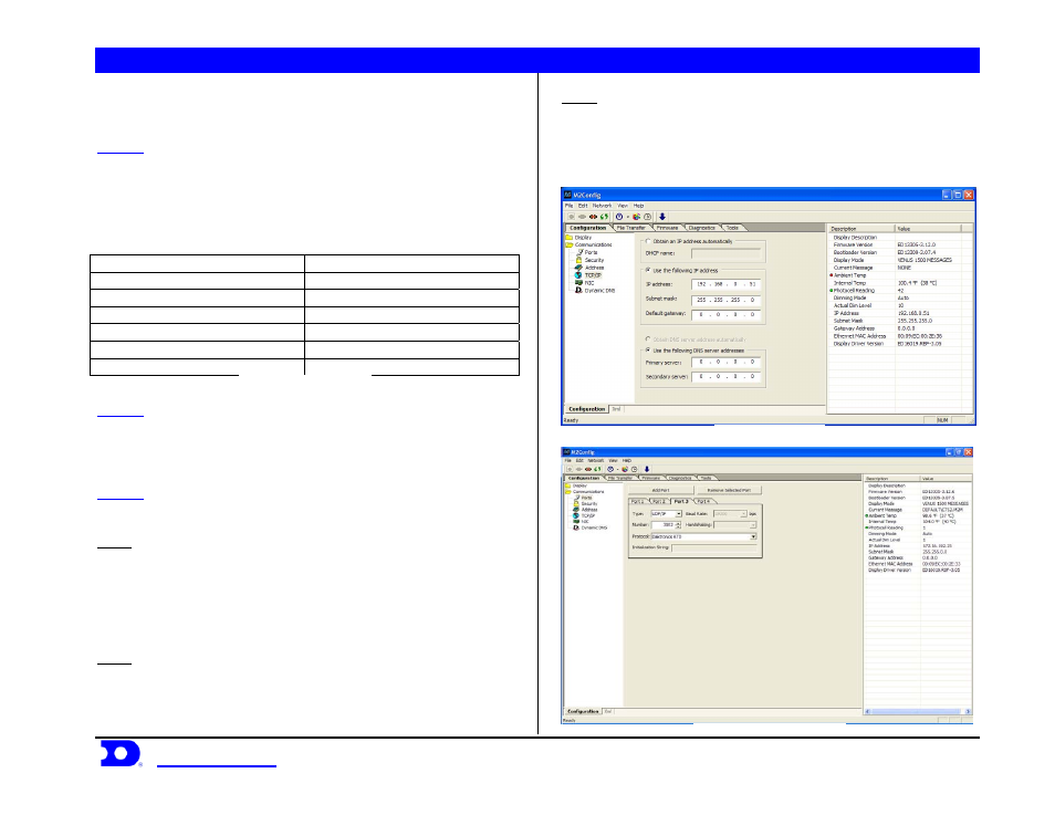
STEP 3:
While connected to the sign, verify that Port 1-3 are set up as
follows:
Port 1
Type:
Direct
Baud Rate: (19,200 for Galaxy Displays)
(115,200 for Galaxy Pro Displays)
Number: 1
Protocol: Venus
1500
Port 2
Type: TCP/IP
Number: 3001
Protocol: Venus
1500
Port 3
Type: UDP/IP
Number: 3002
Protocol: Daktronics
RTD
An example is shown in Figure 9.
Figure 8: TCP/IP settings
Figure 9: M2Config – Port Settings