Daktronics nomenclature, Daktronics nomenclature -2, Figure 2: module numbering example 7x48 front – Daktronics AF-3400-133,171,216,260 User Manual
Page 8: 1 daktronics nomenclature
All references to drawing numbers, appendices, figures, or other manuals are presented in
bold typeface, as shown below.
“Refer to Drawing B-206146 in Appendix A for the power supply connections.”
Additionally, drawings referenced in a particular section are listed at the beginning of that
section as seen in the following example:
Reference Drawing:
Schem; Primary Signal, Internal, W/QC ................................... Drawing B-206146
Daktronics displays are built for long life and require little maintenance. However certain
display components may need replacing. The Replacement Parts List in Section 1 provides
the names and numbers of components that may need to be ordered during the life of the
display. Most display components have a white label that lists the part number. The
component part number is in the following format: 0P-_ _ _ _-_ _ _ _ (component) or 0A-_ _
_ _-_ _ _ _ (multi-component assembly).
Following the Replacement Parts List is the Daktronics Exchange and Repair and
Return Programs in Section 4.12. Refer to these instructions if any display component needs
replacement or repair.
1.1 Daktronics
Nomenclature
To fully understand some Daktronics drawings, such as schematics, it is necessary to
know how various components are labeled in those drawings. This information is
also useful when trying to communicate maintenance or troubleshooting efforts.
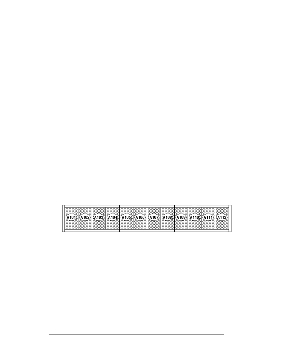
Figure 2: Module Numbering Example 7X48 Front
A module is the building block of the Galaxy display. Each module door for the
133mm/171mm displays measure 7 pixels high by 4 pixels wide. Individual pixels
can be easily removed from the display if required.
Daktronics numbers modules on a Galaxy display.
The following labeling formats might be found on various Daktronics drawings:
•
“TB_ _” signifies a termination block for power or signal cable
•
“F_ _” represents a fuse
•
“E_ _” shows a grounding point
•
“J_ _” denotes a power or signal jack
•
“P_ _” stands for a power or signal plug for the opposite jack
Introduction
1-2