Mechanical installation, Mechanical installation overview, Accessing the display – Daktronics AF-3400-133,171,216,260 User Manual
Page 13: Section 2, Mechanical installation -1, Mechanical installation overview -1, Accessing the display -1, 1 mechanical installation overview, 2 accessing the display
Section 2:
Mechanical Installation
Note: Daktronics does not guarantee the warranty in situations where the display is not
constantly in a stable environment.
The Daktronics engineering staff must approve any changes that may affect the weather-
tightness of the display. If any modifications are made, detailed drawings of the changes must
be submitted to Daktronics for evaluation and approval, or the warranty may be void.
Daktronics is not responsible for installations or the structural integrity of support
structures done by others. It is the customer’s responsibility to ensure that a qualified
structural engineer approves the structure and any additional hardware.
2.1 Mechanical Installation Overview
Because every installation site is unique, there is no single Daktronics-approved
procedure for mounting the Galaxy
®
displays. The information contained in this
section is general information only and may or may not be appropriate for your
particular installation.
A qualified individual must make all decisions regarding the mounting of this
display.
Read both the mechanical and electrical installation sections of this manual
before beginning any installation procedures.
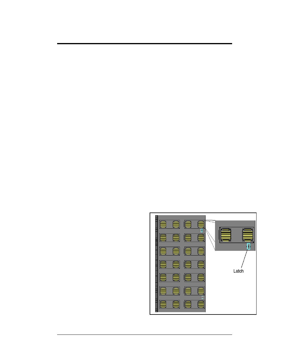
2.2 Accessing the Display
The Daktronics Galaxy
133mm/171mm AF-3400 large
character displays are front accessible;
meaning, access to the internal
components can only be gained from
the front of the display. The module
doors are approximately
20 ½”X41 ½” for the 133mm and
26 ½”X53 ½” for the 171mm and are
7 pixels high by 4 pixels wide. Follow
these steps to open a module door and
access the internal components.
Figure 6: Latch Fastener Locations on Module Door
1. Locate the latch access
fasteners on the module.
Refer to Figure 6 for latch
access fastener locations.
2. With a Phillips head
screwdriver, turn the latch
access fasteners clockwise as
shown in Figure 7
Mechanical Installation
2-1