Power installation, Power connection, Power installation -5 – Daktronics AF-3400-133,171,216,260 User Manual
Page 23: Power connection -5, 6 power connection
as an earth-ground electrode. The support is generally embedded in concrete, and if
in earth, the steel is either primed or it corrodes, making it a poor ground.
A minimum of one grounding electrode must be installed for each display face. The
grounding electrode is typically one grounding rod for each display face. Other
grounding electrodes as described in Article 250 of the National Electric Code may
be used. Daktronics requires that the resistance to ground be 10 ohms or less. If the
resistance to ground is higher than 10 ohms, it will be necessary to install additional
grounding electrodes to reduce the resistance. The grounding electrode should be
installed within 25 feet of the base of the display. The grounding electrode must be
connected to the ground terminal lug on the back of the display.
Power Installation
The power cable must contain an isolated earth-ground conductor. Under this
circumstance, do not connect neutral to ground at the disconnect or at the display.
This would violate electrical codes and void the warranty. Use a disconnect so that
all hot lines and neutral can be disconnected. The National Electrical Code requires
the use of a lockable power disconnect within sight of or at the sign.
3.6 Power
Connection
Reference Drawings:
Schematic, AF-3400-7 (8)X16W/INTC-**-*-P-120/240 1PH... Drawing B-222321
Schematic, AF-3400-7(8)X16 W/INTC-**-P-*, 3PH ................ Drawing B-227282
Schematic, AF-3400-7(8)X16W/INTC-**-*-_240 1PH ............ Drawing B-228917
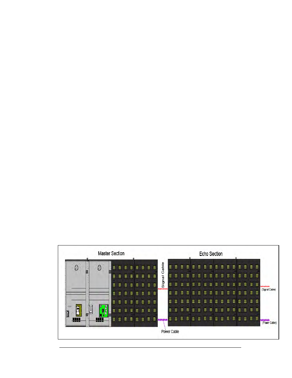
The display is divided into sections, and each section is made up of four (4) module
doors. The “master” section, which is the first section of the display, receives the
initial power and communication signaling. The power and communication signal
wires daisy chain from the master section to the proceeding “echo” section. That
“echo” section then daisy chains the signal and power to the following section and so
on. Refer to the appropriate Schematic Drawing for the your particular displays
voltage, and Figure 16 to better understand the signaling system.
Figure 16 Cable Connections Between Master and Echo Sections
Electrical Installation
3-5