Service and diagnostics, Transformer and rfi filter, Transformer – Daktronics AF-3400-133,171,216,260 User Manual
Page 30: Rfi filter, Controller, Service and diagnostics -4, Transformer and rfi filter -4, Controller -4, Figure 19: power termination box, 4 service and diagnostics
4.4 Service
and
Diagnostics
Reference Drawings:
Schematic, AF-3400-7 (8)X16W/INTC-**-*-P-120/240 1PH........ Drawing B-222321
The following sub-sections address servicing of the following display components:
•
transformer, RFI filter
•
controller
•
modules, drivers and power supplies
•
Remember: Disconnect power before servicing any internal components.
Transformer and RFI Filter
Maintenance and Troubleshooting
4-4
f
Trans ormer
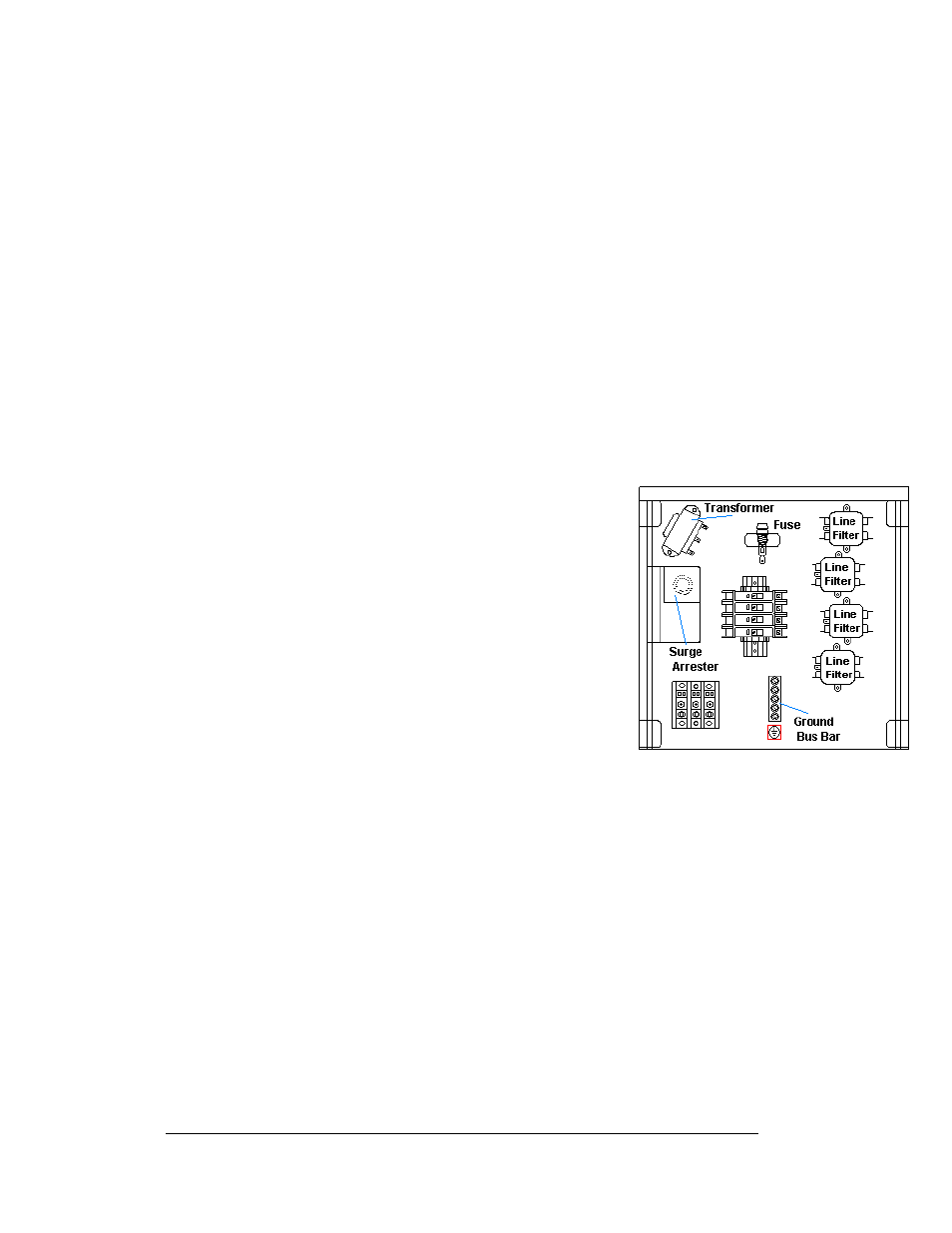
Figure 19: Power Termination Box
The transformer is located in the upper portion of the power
termination box as
transformer, first disconnect and label all the wires attached
to it. Turn off power to the display before removing the
wires. Then release the hardware, securing it to the inside of
the enclosure. Position the new transformer in its place, and
tighten it down. Re-connect all the wires using Drawing B-
222321 as a reference.
RFI Filter
The RFI electrical filters are mounted within the power
termination box. Like the transformer, first removing all
connecting wires, and then releasing the attachment hardware
can replace the filters. Install the new filter using Drawing
B-222321 as a wiring reference.
Controller
The controller sends data to the modules. Refer to the signal summary in Section 4.2
for more information.
illustrates a typical controller.
The Rotary switches set the hardware address, which the software uses to identify
that particular display. When replacing a controller board, be sure to set the rotary
switches in the same address configuration as the defective controller. Each
controller in a network needs a unique address.
Note: Setting the rotary switches to address 0 (set the switches to 0 by rotating them
counter clockwise until the arrow points to 0) can activate a test mode. The display’s
power must be turned off, and then turned back on to run the test mode.