Support structure design, Support structure design -2, Figure 7: opening the module door -2 – Daktronics AF-3400-133,171,216,260 User Manual
Page 14: 3 support structure design
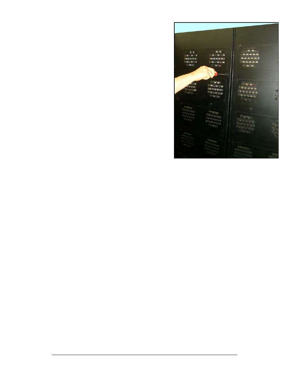
Figure 7: Opening the Module Door
3. Gently pull the module door forward.
4. Gently open the door. The wires
connected to the module door provide
enough slack to open the module door,
however, if you want to remove the door
you will have to disconnect the wires.
2.3 Support Structure Design
Support structure design depends on the mounting methods, display size, and weight.
The structure design is critical and should be done only by a qualified individual.
Display height and wind loading are also critical factors. It is the customer’s
responsibility to ensure that the structure and mounting hardware are adequate.
Daktronics is not responsible for the installations or the structural integrity of
support structures done by others.
It is the installer’s responsibility to ensure the mounting structure and
hardware are capable of supporting the display and will agree with local codes.
Before beginning the installation process, verify the following:
•
All clip angles or mounting holes must be attached to the support structure
•
The mounting structure will provide a straight and square-mounting frame
for the display
•
The mounting structure is capable of supporting the display and will not
yield at any unsupported points after mounting
•
Make sure that 3" of unobstructed space is available above the top of the
display to remove the eyebolt.
Note: No clearance is required once the eyebolt is removed. Correct any deficiencies
before installation.
Mechanical Installation
2-2