Power summary, Power summary -3, Figure 18: power routing -3 – Daktronics AF-3400-133,171,216,260 User Manual
Page 29: 3 power summary
4.3 Power
Summary
Reference Drawings:
Schematic, AF-3400-7 (8)X16(A)-***-*-p, 120, 120/240 ....... Drawing B-211433
Schematic, Power Supply Configuration............................... Drawing A-215504
Schematic, AF-3400-7 (8)X16W/INTC-**-*-P-120/240 1PH . Drawing B-222321
Refer to Drawing B-211433 and Drawing B-222321, located in Appendix A, for
your particular display. The power routing for the display can be summarized as
follows:
The power routing for the display can be summarized as follows:
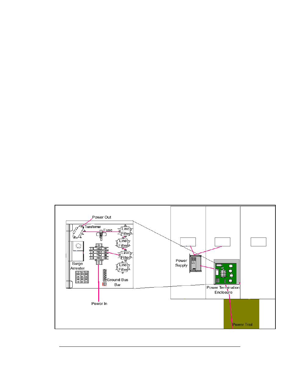
1. Incoming power terminates at the power termination enclosure. Before
leaving the enclosure, power is sent through a circuit breaker and an RFI
electrical filter as shown in Figure 18.
2. Power for the controller board passes through a transformer located on the
controller/power panel.
3. Power supplies are used to power the modules. Power supplies are preset.
Contact Daktronics Customer Service for the proper settings.
4. Monochrome Galaxy displays use red and amber LEDs. Each 12.5 VDC
power supply provides power to two module doors in a display that uses 24
red LEDs per pixel board. Each 13VDC power supply provides power to
two modules in a display that uses 24 amber LEDs per pixel board
Figure 18: Power Routing
Maintenance and Troubleshooting
4-3