Section 2: mechanical installation, 1 support structure requirements, Section 2 – Daktronics AF-3400-12-RGB User Manual
Page 9: Mechanical installation, Support structure requirements, Figure 3: back view of typical display
Section 2:
Mechanical Installation
• Daktronics engineering staff must approve any changes to the display. If any
modifications are made, detailed drawings of the changes must be submitted to
Daktronics for evaluation and approval, or the warranty may be void.
Daktronics is not responsible for installations or the structural integrity of
support structures done by others. The customer is responsible for ensuring
that a qualified structural engineer approves the structure and any hardware.
2.1 Support Structure Requirements
Because every installation site is unique, no single procedure is approved by Daktronics for
mounting Galaxy
®
displays. The information contained in this section is general information
only and may or may not be appropriate for this particular installation.
A qualified individual must make all decisions regarding the mounting of this display.
Support structure design depends on the mounting methods, display size, and weight. In
general, the front of the display needs to be unobstructed to allow for air flow and internal
access. The bottom of the display houses the fans so allowances will need to be made for their
operation. Also keep in mind the location of the mounting clips and the power/signal
termination box or knockouts on the back of the display. Display height and wind loading
are also critical factors to be considered. This information can be found in the Shop drawing
provided with the display.
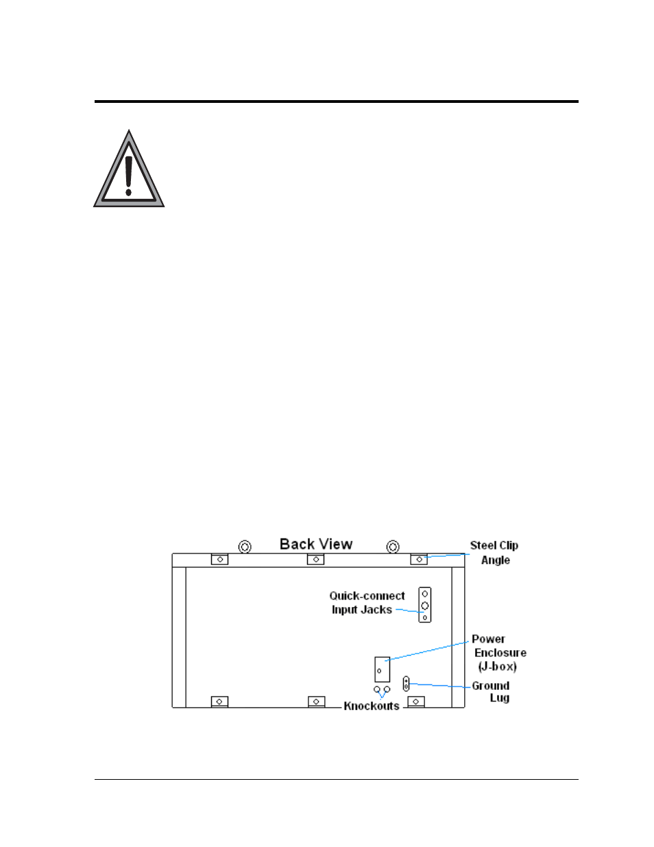
The external components and their typical location are shown in Figure 3. Refer to the
specific shop drawing for the actual dimensions and location of components in a particular
display.
Figure 3: Back View of Typical Display
Mechanical Installation
3